


A 48v lifepo4 battery is one of the most widely used building blocks in low-voltage solar battery storage systems. For commercial PV professionals, its appeal is straightforward: lithium iron phosphate chemistry offers strong safety characteristics, long cycle life, high usable depth of discharge, and modular deployment in rack-mounted, wall-mounted, or cabinet-based systems. That makes it a practical option for small commercial rooftops, telecom sites, clinics, farms, offices, backup power systems, and hybrid or off-grid PV projects.
However, specifying a 48V battery for a professional solar project is not simply a matter of choosing the lowest price per kWh. EPCs, installers, and system integrators must evaluate voltage range, usable capacity, certifications, installation environment, communication protocols, protection design, warranty conditions, and lifecycle economics.
This guide explains how to evaluate a 48v lifepo4 battery from a commercial PV perspective. It focuses on real project decisions: when 48V architecture makes sense, how to size a battery bank, how to avoid commissioning problems, what certifications matter, how to assess suppliers, and how to compare lifecycle value rather than only upfront cost.
Most products sold as 48V LiFePO4 batteries are actually 51.2V nominal battery packs. These systems are typically built as 16S (16 cells in series), where each lithium iron phosphate cell has a nominal voltage of around 3.2V, resulting in a 51.2V nominal system voltage. At full charge, a 16S LiFePO4 battery typically reaches around 58.4V when each cell is charged to approximately 3.65V. Depending on manufacturer settings and BMS configuration, the recommended charging voltage range is typically around 56.8V to 58.4V to balance performance and battery longevity. The low-voltage cutoff range is commonly around 40V to 46V, depending on the inverter settings and battery management system protection strategy. These systems are built using a 16S configuration with lithium iron phosphate cells, which defines the standard voltage structure used in most 48V-class batteries.
This voltage class is popular because it provides a useful balance between safety and practical power delivery.
However, 48V systems do not eliminate electrical hazards such as arc flash risk, short-circuit current, thermal runaway, or overcurrent events, which must still be managed through proper design and protection devices.
Compared with high-voltage battery systems, 48V architectures reduce electrical shock risk and are easier to handle during installation and maintenance.
Compared with 12V or 24V systems, a 48V architecture reduces current for the same power output, which can reduce cable size and losses. Compared with high-voltage battery systems, it remains easier to handle, more modular, and often simpler for smaller commercial projects.
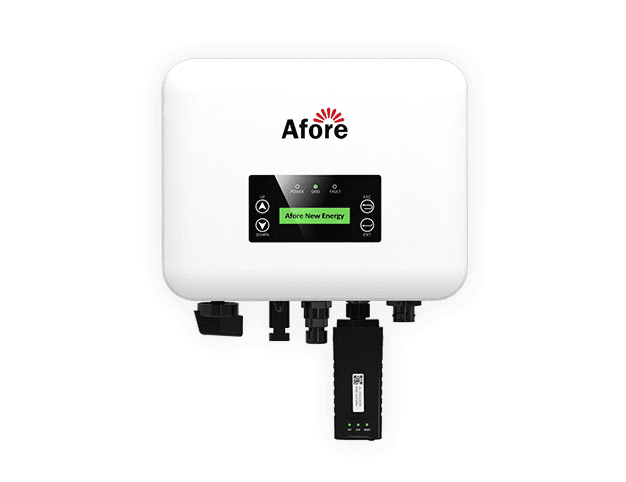
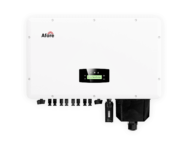
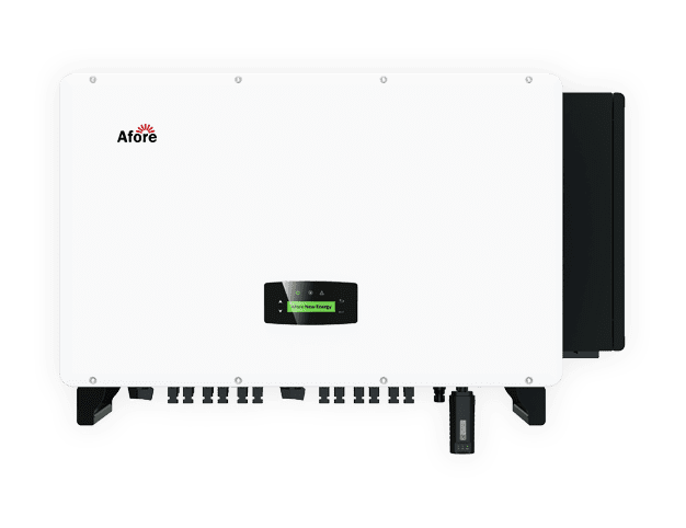
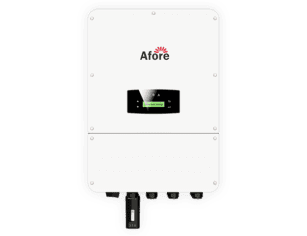
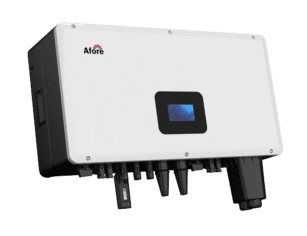
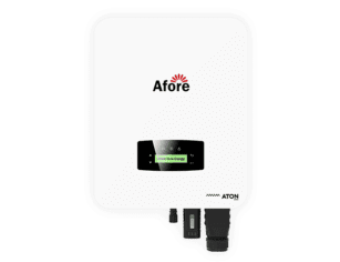
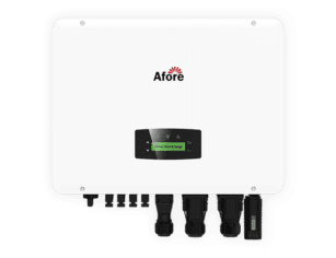
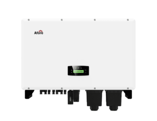
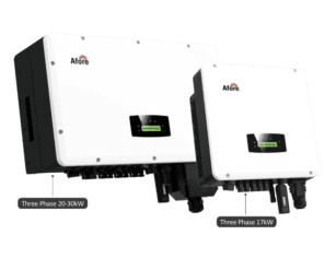
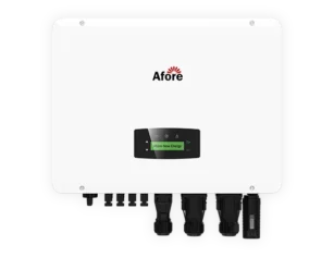
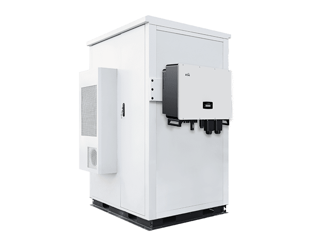
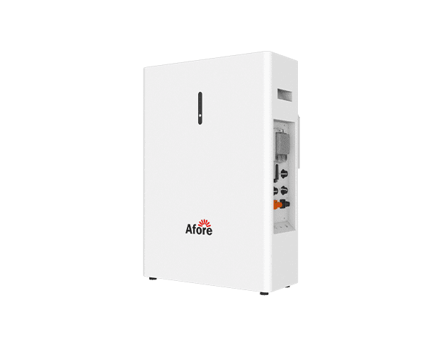
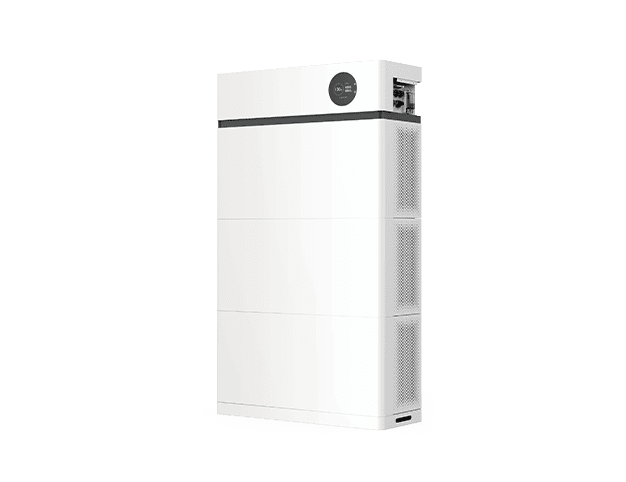
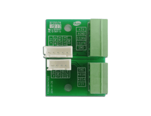
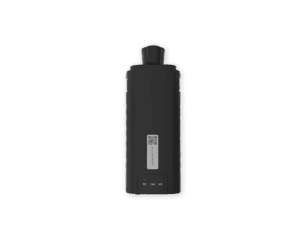
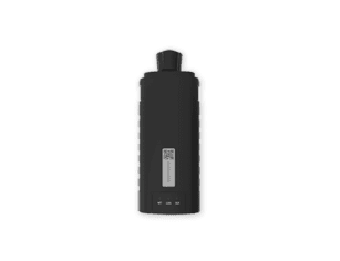
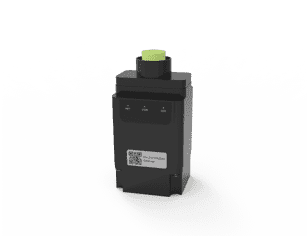
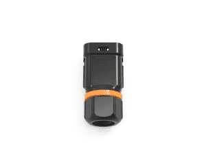
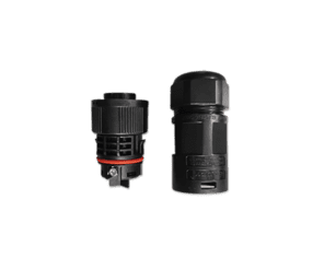
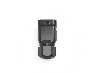
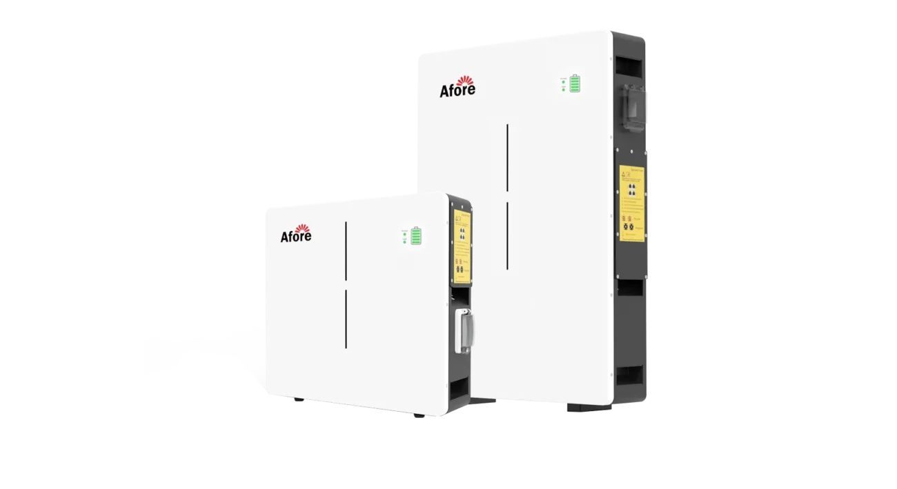
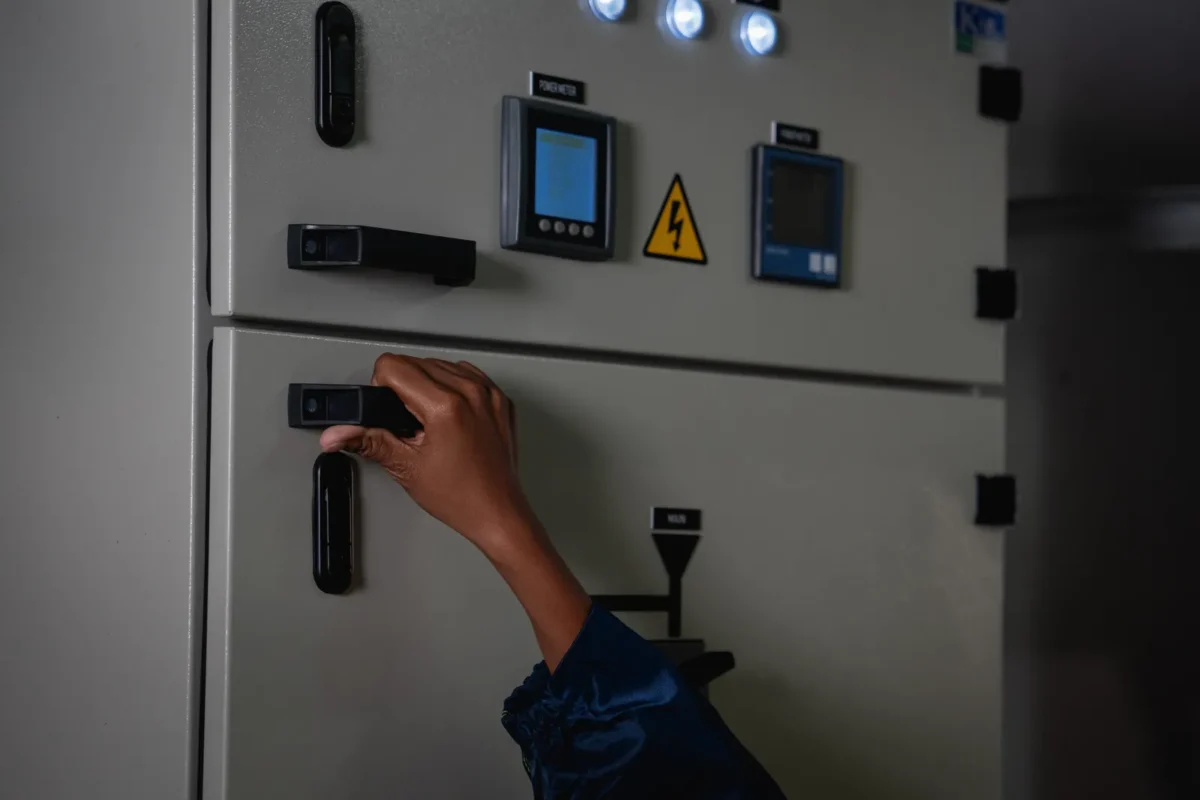
A 48V lithium iron phosphate battery may be supplied as a rack-mounted lithium battery module, a wall-mounted unit, or a modular cabinet system. Common module sizes include 51.2V 100Ah systems with approximately 5.12 kWh of capacity, and 51.2V 200Ah systems with approximately 10.24 kWh of nominal capacity. Rack-mounted batteries are especially common in professional PV and telecom applications because they allow capacity to be expanded by adding modules in parallel, provided the inverter, BMS, busbars, cables, and protection devices are designed for the total current.
For commercial projects, the most common mistake is comparing batteries only by nameplate kWh. Usable energy, discharge limits, communication compatibility, certifications, and thermal derating are often more important than rated capacity.
EPC teams should evaluate performance under real operating conditions rather than relying on datasheet specifications alone.
The most important specifications to verify are summarized below.
| Parameter | Why it matters in commercial PV projects |
|---|---|
| Nominal voltage and operating voltage range | Must match the inverter or charger battery input window |
| Rated and usable capacity | Determines real backup duration or self-consumption value |
| Maximum charge/discharge current | Limits power output and charging speed |
| Continuous and peak C-rate | Affects suitability for motor loads, pumps, HVAC, and surge events |
| Tiefe des Abflusses | Impacts usable energy and long-term degradation |
| Cycle life conditions | Must be checked against DoD, temperature, and C-rate assumptions |
| BMS communication | Required for accurate SOC, protection coordination, and warranty compliance |
| Zertifizierungen | Important for transport, permitting, insurance, and commercial acceptance |
| Betriebstemperatur | Critical for hot climates, outdoor cabinets, and cold charging conditions |
| Garantiebedingungen | Must align with expected cycles, throughput, temperature, and approved inverter use |
A datasheet that looks attractive at first glance may become less competitive once the project team calculates usable energy, required battery quantity, additional BOS components, and service risk.
A 48V LiFePO4 battery is commercially appropriate where the project requires moderate power, modularity, serviceability, and manageable low-voltage installation.
From a system design perspective, 48V architectures become progressively more challenging as power levels increase because current rises significantly at lower voltage.
As a general design review framework, 5–10 kW systems are typically well suited for 48V architecture, while 10–20 kW systems remain feasible but require careful attention to current rating, cable sizing, and protection coordination.
Above approximately 20 kW, system designers should actively re-evaluate whether a high-voltage battery architecture would provide better efficiency and lower installation complexity.
For larger commercial systems involving hundreds of kWh of storage or long DC cable distances, high-voltage architectures are often preferred due to reduced current and improved system efficiency.
These thresholds should be treated as design review triggers rather than strict technical limits, since final system suitability depends on load profile, inverter design, and installation conditions.
Common applications include small commercial PV with backup, telecom power systems, remote monitoring sites, clinics, retail sites, agricultural facilities, small workshops, and hybrid PV systems using low-voltage Hybrid-Wechselrichter.
In many global markets, 48V systems are especially attractive for projects in the range of several kWh to several tens of kWh. They are also useful where installers need a battery platform that can be stocked, transported, replaced, and expanded without the complexity of high-voltage battery strings.
However, 48V is not suitable for every commercial facility, especially where higher power demand or long cable runs are required. Larger C&I systems with high power demand, long DC cable runs, centralized energy storage rooms, or hundreds of kWh of capacity may be better suited to high-voltage battery systems. The reason is electrical: at 48V, power requires high current. High current increases cable size, voltage drop, heat, and protection complexity. For example, a 20 kW discharge at roughly 50V can require around 400A before considering losses. That is possible, but it requires careful busbar, cable, breaker, and thermal design.
Low-cost batteries can be suitable when they are properly certified, documented, and supported. The risk is not low price itself; the risk is incomplete evaluation. Commercial PV projects are exposed to installation schedules, warranty claims, client expectations, and sometimes financing or insurance review. A battery that works in a simple standalone setup may not be suitable for a professional solar battery storage system.
The most common hidden risks include BMS communication that is not supported by the selected inverter, limited certification coverage, vague cycle-life claims, poor cell consistency, weak after-sales support, unclear RMA procedures, and installation manuals that do not meet local permitting expectations. For resellers, these issues can become channel risk. For EPCs, they can create commissioning delays, repeat truck rolls, and reputational damage with commercial clients.
Lithium iron phosphate, usually abbreviated as LiFePO4 or LFP, is widely used in stationary energy storage because it prioritizes safety, stability, and lifecycle performance. Compared with several other lithium-ion chemistries, LFP is generally known for stronger thermal stability and a lower tendency toward thermal runaway under abusive conditions. This does not remove the need for professional system design, but it is one reason LFP has become a preferred chemistry for solar ESS, telecom backup, and other stationary applications.
The International Electrotechnical Commission provides broader context on energy storage system safety, interoperability, and standardization for modern power systems, with detailed guidance available from IEC Energy Storage Standards.
AC-coupled systems typically have higher conversion losses than DC-coupled systems because energy passes through multiple power conversion stages between PV, battery, and load.
For commercial PV stakeholders, the value of LFP is not only chemical safety. It also tolerates frequent cycling better than lead-acid batteries, supports higher usable depth of discharge, has relatively high round-trip efficiency, and requires less routine maintenance. These characteristics are particularly important in PV self-consumption, off-grid, and hybrid systems where daily charge and discharge cycles are expected.
A professionally specified 48V LiFePO4 battery commonly offers thousands of cycles. Many commercial products are marketed in the range of approximately 3,000 to 8,000 cycles, depending on cell quality, depth of discharge, charge and discharge rate, ambient temperature, and the manufacturer’s warranty assumptions. In practical terms, a system cycling once per day may be designed for around 10 years or more, but the real outcome depends heavily on operating conditions.
Project teams should avoid relying only on headline cycle-life numbers. A claim of 6,000 cycles is meaningful only if the test conditions are clear. Was the test performed at 80% DoD or 100% DoD? At 25°C or a higher ambient temperature? At 0.5C or 1C? What capacity retention threshold defines end of life: 80%, 70%, or 60% remaining capacity? These details matter because commercial systems are often operated in warm rooms, outdoor cabinets, or high-cycling conditions that may differ from laboratory assumptions.
Depth of discharge describes how much of the battery’s stored energy is used during a cycle. A battery rated at 10 kWh may not provide 10 kWh of practical usable energy if the BMS reserves a portion of capacity to protect the cells. Many LiFePO4 systems allow 80–95% usable DoD, but the warranty may be based on a specific operating window.
For EPCs, usable capacity should be modeled according to the project objective. A backup system for a clinic may need conservative usable capacity because resilience is more important than maximizing each cycle. A PV self-consumption system may accept deeper daily cycling if the tariff benefit justifies faster degradation. An off-grid agricultural site may require additional margin to recover from cloudy periods without pushing the battery bank into frequent low-SOC operation.
The important point is that usable capacity is a system design value, not only a product value. It depends on the battery, inverter settings, BMS limits, ambient temperature, and the load profile.
Energy capacity and power output are often confused. Battery capacity is measured in kWh, while power is measured in kW. A 20 kWh battery bank may not be able to supply a 20 kW load unless the modules, BMS, busbars, cables, and inverter are rated for that discharge current.
C-rate is a useful way to interpret power capability. A 100Ah battery discharged at 100A is operating at 1C. The same battery discharged at 50A is operating at 0.5C. Many 48V LiFePO4 battery modules are designed for continuous operation around 0.5C to 1C, with short peak capability above that for limited durations. Commercial loads with motors, pumps, compressors, HVAC, refrigeration, or inductive equipment require special attention because startup currents may exceed normal running current.
Where surge loads are expected, the battery bank should be checked together with the inverter overload rating. Adding more battery modules in parallel may improve available current, but only if the manufacturer permits the configuration and the current-sharing design is correct.
The choice between a low-voltage 48V battery system and a high-voltage battery system is one of the most important architecture decisions in commercial PV storage.
While 48V systems reduce electrical shock risk and are easier to handle during installation, they introduce higher current levels that increase design complexity in cables, busbars, and protection devices. This creates a fundamental trade-off between reduced voltage risk and increased high-current engineering requirements.
A 48V system offers easier modularity, reduced shock risk, broad availability of hybrid and off-grid inverters in smaller power classes, and practical field serviceability. It is often suitable for small commercial and remote sites where system size is moderate.
High-voltage systems are commonly used in larger commercial and industrial projects because they reduce current for the same power level. Lower current can improve system efficiency, reduce cable size, simplify high-power inverter integration, and support larger centralized storage designs. However, high-voltage systems usually require stricter installation procedures, specialized safety practices, and more integrated battery-inverter platforms.
| Auslegungsfaktor | 48V LiFePO4 system | High-voltage battery system |
|---|---|---|
| Typical project fit | Small commercial, telecom, off-grid, backup | Larger C&I and utility-scale ESS |
| Strom bei gleicher Leistung | Höher | Unter |
| Cable size and voltage drop | More demanding at higher power | Easier at high power |
| Modularity | Strong for rack/cabinet expansion | Strong in engineered rack systems |
| Komplexität der Installation | Lower voltage, but high current | Higher voltage safety requirements |
| Inverter class | Common in 5–20 kW hybrid/off-grid range | Common in larger C&I systems |
| Skalierbarkeit | Practical to tens of kWh, sometimes more | Better for large energy and power capacity |
The practical decision is not about which architecture is “better.” It is about which architecture matches the inverter class, power requirement, site layout, service model, and future expansion plan.
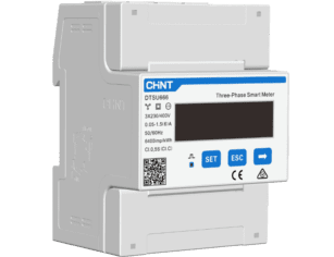
A 48V LiFePO4 battery cannot be assumed to work with any Solarwechselrichter. Compatibility depends on the inverter’s battery voltage window, maximum charge and discharge current, charging profile, BMS communication protocol, firmware, and approved battery list.
In professional systems, closed-loop communication is strongly preferred. This allows the battery BMS to send state of charge, state of health, charge current limits, discharge current limits, temperature alarms, and protection status to the inverter. Common communication interfaces include CAN, RS485, Modbus-based implementations, and dry contact signals. The physical communication port is not enough; the protocol must also be supported by both devices.
If the battery is not on the inverter’s compatibility list, the project team should obtain written confirmation from the battery and inverter suppliers before procurement. Open-loop operation may be possible in some systems using voltage-based charging parameters, but it can reduce SOC accuracy and may affect warranty coverage.
A 48V LiFePO4 battery can be integrated into different PV system architectures. In a DC-coupled design, solar generation, battery charging, and inverter conversion are coordinated through a hybrid or off-grid inverter. This is common in new installations where backup power, self-consumption, or off-grid operation is required.
In an AC-coupled design, battery storage is connected through a battery inverter on the AC side of an existing PV system. In AC-coupled systems, the battery is connected to a dedicated battery inverter. The battery inverter is then connected to the AC bus of the site electrical system. Existing grid-tied PV inverters remain connected on the AC side and operate independently of the battery system. During backup or islanded operation, coordination between the battery inverter and PV inverters is required to maintain stable system operation and load balance.
This can be useful for retrofits, especially where a commercial site already has grid-tied PV inverters installed. AC coupling may simplify integration with existing PV assets, but it requires careful control of export limits, backup loads, grid charging rules, and inverter coordination during outages.
The U.S. Department of Energy provides a useful overview of solar-plus-storage concepts and the role of batteries in shifting solar energy availability, as explained in DOE Solar Plus Storage Overview.
For commercial projects, the architecture should be selected according to the operating objective. Backup power, diesel reduction, self-consumption, grid charging, peak demand control, and export limitation all place different demands on the battery and control system.
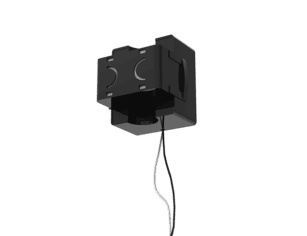
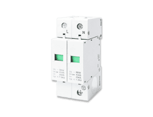
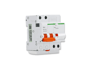
The balance of system is especially important in 48V battery installations because high current can create heat, voltage drop, nuisance trips, and protection coordination issues. A professional installation normally requires correctly rated DC breakers or fuses, isolators, battery cables, lugs, busbars, combiner boxes, grounding or bonding arrangements, surge protection where applicable, monitoring hardware, and a suitable enclosure or cabinet.
Cable sizing should be based on continuous current, peak current, route length, allowable voltage drop, ambient temperature, installation method, and local electrical code. A cable that appears adequate for short test operation may run too hot under daily cycling. Similarly, loose terminals, poor crimping, or incorrect torque settings can lead to resistance heating and long-term reliability problems.
Sizing begins with the load profile, not the battery catalogue. Commercial projects should use measured energy data wherever possible, especially when backup power or off-grid operation is part of the scope. Daily kWh consumption, peak load, starting currents, operating hours, solar generation profile, autonomy requirement, and allowable DoD all influence battery size.
A simplified sizing process follows three core relationships:
Required nameplate capacity = Required usable energy ÷ Allowed usable DoD
Battery current ≈ Power ÷ Battery voltage
Number of modules = Required nameplate capacity ÷ Energy per module
These equations separate energy sizing, electrical current verification, and system modularization.
A simplified sizing process is shown below.
| Step | Design question | Practical output |
|---|---|---|
| 1 | What loads must be supported? | Critical-load list or full-site load profile |
| 2 | How long must backup last? | Required usable kWh |
| 3 | What is the peak and surge power? | Inverter and battery current requirement |
| 4 | What DoD is allowed? | Nameplate battery capacity |
| 5 | How much PV recharge is available? | Autonomy and recovery calculation |
| 6 | What expansion is expected? | Cabinet, busbar, and inverter planning |
For example, if a small clinic requires 18 kWh of usable backup energy for critical lighting, refrigeration, IT, and medical support loads, and the design uses 90% usable DoD, the required nameplate capacity is about 20 kWh before additional design margin.
If each 48V battery module provides 5.12 kWh of capacity, the system requires approximately four modules to meet the energy requirement.
At the same time, power delivery must also be verified. A 10 kW load corresponds to approximately 195A at 51.2V, while a 20 kW load corresponds to approximately 391A.
However, module count alone is not sufficient for final design approval. EPC teams must also confirm whether the selected inverter supports parallel operation of the required number of modules, whether the BMS communication addressing is compatible, and whether the system can safely deliver the required discharge current under real operating conditions.

The value of a 48V LiFePO4 battery depends on the operating strategy. In PV self-consumption applications, the battery stores surplus daytime solar generation and discharges during evening or non-solar hours. This is valuable where export compensation is low or where grid electricity prices are high.
For backup power, the value case is different. The battery may sit at a higher SOC and cycle less frequently, but it provides resilience during outages. In clinics, telecom shelters, retail sites, farms, and small data rooms, outage cost can be more important than energy arbitrage.
In diesel-hybrid systems, storage can reduce generator runtime, improve generator loading, and store PV energy that would otherwise be curtailed. In limited peak-shaving applications, the battery may discharge during short demand peaks, but this requires careful modeling because 48V systems may be constrained by high current at larger power levels.
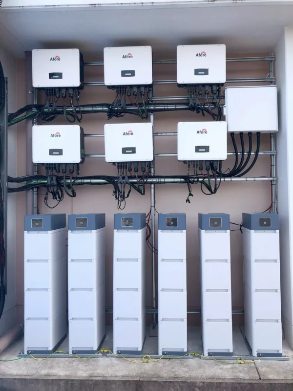
Rack-mounted LiFePO4 battery modules are often connected in parallel to increase system capacity while maintaining a 48V architecture.
Before paralleling, all battery modules should be brought to similar state of charge (SOC) and voltage levels to minimize inrush current and current imbalance during connection.
This is one of the main advantages of modular low-voltage storage, but it also introduces engineering constraints that must be controlled in system design.
Parallel battery connections should use equal-length cables or a properly rated DC busbar to ensure balanced current sharing.
Parallel expansion must always follow manufacturer-defined limits and approved wiring topology.
High-current daisy-chain wiring should be avoided unless explicitly approved by the battery manufacturer, as it can cause uneven current distribution and overheating risks.
Manufacturer-approved communication addressing and configuration must be used to ensure proper BMS coordination across all parallel modules.
Practical design constraints include maximum parallel module quantity, inverter current capability, busbar rating, cable symmetry, and firmware compatibility.
Each battery module may require individual fusing or breaker protection depending on system design and manufacturer specifications to ensure safe fault isolation.
The maximum allowable number of parallel modules must always be verified against manufacturer documentation and certification limits.
For long-term system stability, expansion planning should be considered at the design stage.
Mixing old and new battery modules is only acceptable when explicitly permitted by the manufacturer, due to differences in internal resistance, capacity fade, and cycle history.
Pre-charge circuits or anti-spark procedures should be implemented to protect inverter capacitors and prevent inrush current damage during system startup.
Many commercial facilities start with modest storage capacity and expand after tariff changes, load growth, or operational experience. A 48V battery platform can support this strategy, but only if the system is designed for expansion.
Mixing old and new batteries can be challenging because module age, internal resistance, firmware, cell batch, and BMS settings may differ. Some manufacturers restrict expansion after a certain time window. Others require all modules to be updated to compatible firmware before connection. EPCs and resellers should clarify these rules before presenting a battery line as “easily expandable.”
For commercial procurement, certifications are not optional paperwork. They influence transport, permitting, insurance, project finance, and customer acceptance. Common standards and documentation areas include UN38.3 for transportation of lithium batteries, IEC 62619 for industrial lithium battery safety, UL 1973 for stationary battery systems, UL 9540 for energy storage system (ESS) certification, and CE, EMC, and other electrical safety requirements depending on the target market.
UL 9540A is commonly referenced as a thermal runaway and fire propagation test method used to evaluate energy storage system safety under extreme conditions. NFPA 855 provides installation safety requirements for energy storage systems in the United States, with specific guidance on fire protection, system layout, and installation conditions. The International Fire Code (IFC), along with local fire authority requirements, may also apply depending on jurisdiction and permitting authority. IEC 62933 provides a broader framework for electrical energy storage system performance, safety, and system-level standardization.
Certification requirements can be understood in several layers: cell-level safety, battery module certification, ESS-level certification, inverter grid compliance, and final site-level approval. Each layer addresses different aspects of safety and performance validation across the full system lifecycle.
UL provides information on testing and certification services for batteries and energy storage systems, including stationary storage safety considerations, detailed in UL Energy Storage Testing and Certification.
Certification expectations vary by country, authority having jurisdiction, insurer, project size, and installation environment. A structured compliance hierarchy in commercial battery systems typically includes cell-level safety certification, battery module-level safety certification, rack or cabinet-level energy storage system (ESS) certification, inverter grid compliance certification, and final site-level electrical and fire-code approval. A battery acceptable for a private off-grid installation may not satisfy the documentation requirements for a commercial building, public facility, or financed C&I project.
LiFePO4 chemistry is more thermally stable than many other lithium-ion chemistries, but system-level safety depends on installation design, protection devices, and operating conditions.
From a practical engineering perspective, LiFePO4 batteries should not be charged below 0°C unless they include internal heating, low-temperature charge protection, or external thermal management. Charging outside this range can trigger BMS protection or accelerate degradation.
Thermal runaway propagation testing such as UL 9540A is used at system level to evaluate how battery modules behave under extreme failure conditions and whether fire can propagate between units.
Outdoor or cabinet-based installations require adequate clearance between battery racks, ventilation pathways, and fire-rated separation where specified by local code. Emergency shutdown (E-Stop) functionality should be integrated at system level to isolate DC power during fault conditions.
Fire safety compliance also depends on proper documentation, including fire-code alignment (such as NFPA 855 or IFC requirements where applicable), installation layout drawings, and system-level safety certification.
It is important to distinguish between cell-level safety, battery module certification, and full energy storage system (ESS) certification, as each layer addresses different failure modes and compliance requirements.
In cold climate deployments, battery cabinets should include insulation, heating systems, or HVAC-controlled temperature management to ensure the system operates within approved BMS limits.
Grid compliance is usually driven by the inverter and complete system configuration rather than the battery alone. In North America, requirements often involve inverter standards and interconnection rules linked to UL 1741 and IEEE 1547. In parts of Europe, grid connection may involve EN 50549-related requirements or national rules such as G99-type processes. Other regions have local utility interconnection procedures that must be confirmed before design finalization.
The key point for EPCs is that battery-inverter combinations should be verified during permitting, not after installation. Grid compliance approval is typically divided into multiple layers, including battery system approval, inverter grid compliance certification, full system integration approval, and final site-level electrical and utility interconnection approval. Each layer must be validated independently to ensure the complete system meets regulatory, safety, and utility requirements.
A technically compatible battery may still cause approval issues if the documentation package is incomplete or if the inverter configuration does not meet local anti-islanding, frequency response, export control, or remote disconnection requirements.
Commercial projects usually require a more complete documentation package than small consumer installations. The exact requirements vary, but EPCs and resellers should be prepared to provide the following:
Incomplete documentation can delay commercial PV approvals, inspections, and insurer reviews. It can also weaken the EPC’s position if warranty disputes occur later.
A 48V LiFePO4 battery system may be modular and compact, but it still requires professional site preparation. Floor or wall load capacity should be confirmed for racks, cabinets, or wall-mounted units. Service clearances should allow safe access to terminals, breakers, communication ports, and removable modules. Cable routing should minimize voltage drop and avoid mechanical damage.
The installation environment should be reviewed for ambient temperature, humidity, dust, water exposure, corrosive atmosphere, restricted access, ventilation, and fire separation. In commercial settings, the battery area should be clearly labeled and protected from unauthorized handling. If the system supports critical loads, the battery location should also be evaluated for resilience during flooding, overheating, or building service interruptions.
Commissioning is where many battery issues are discovered, and a structured process reduces early-stage failures. Installers should confirm mechanical installation, polarity, torque settings, cable size, DC protection, grounding or bonding requirements, communication wiring, DIP switch or address settings, firmware versions, inverter battery profile, charge and discharge limits, SOC calibration, alarm status, and remote monitoring connection.
A short initial charge-discharge test is useful for confirming that the inverter recognizes the battery correctly, the BMS reports stable data, and current is shared correctly across modules. Baseline data should be saved because it may be needed for warranty claims, future troubleshooting, or performance verification.
Common errors include undersized cables, poor crimping, incorrect inverter settings, reversed polarity, insufficient ventilation, and unbalanced wiring in parallel battery systems.
In addition to these issues, parallel system configuration errors are a frequent source of performance degradation in commercial installations.
Common parallel connection mistakes include mismatched state of charge before installation, unequal cable lengths creating resistance imbalance, missing or incorrectly sized protection devices, improper communication addressing between battery modules, and failure to follow manufacturer-approved parallel wiring topology.
These issues can lead to uneven current sharing, nuisance BMS alarms, accelerated degradation of specific modules, and reduced overall system efficiency.
Proper commissioning should always include verification of cable symmetry, SOC matching, communication integrity, protection coordination, and current balancing across all parallel battery strings.
Commercial customers care about uptime. A battery system that is difficult to service may become expensive even if its purchase price is attractive. EPCs should consider front-access design, replaceable modules, spare parts availability, remote diagnostics, firmware update procedures, and clear warranty replacement logistics.
For telecom sites, clinics, and small data rooms, downtime affects more than energy savings. It can affect business continuity. This makes serviceability a procurement criterion, not just an O&M concern.
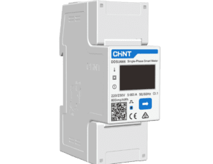
The battery management system is the operational core of a 48V lithium iron phosphate battery pack. Battery performance should be evaluated across three efficiency layers: battery DC efficiency at the cell/module level, inverter conversion efficiency, and full system round-trip efficiency from AC to DC and back to AC in real operation. It monitors and protects the cells while communicating with the inverter or monitoring platform. For commercial O&M, the most useful data includes SOC, SOH, pack voltage, current, temperature, cell voltage deviation, cycle count, alarm history, charge/discharge events, and BMS protection actions.
This data helps identify abnormal behavior before it becomes a site failure. For example, rising cell imbalance may indicate a module issue, thermal stress, or irregular current sharing. Repeated overcurrent alarms may point to an undersized battery bank or unexpected load behavior.
Remote monitoring is increasingly important for EPCs and resellers managing multiple distributed PV-plus-storage sites. Cloud dashboards, inverter portals, battery monitoring systems, API access, and alert notifications can reduce truck rolls and improve service response. The best monitoring setup is one that provides consistent data across sites, not just a basic “online/offline” status.
For channel businesses, monitoring also supports warranty validation. If a customer operates the battery outside approved temperature, current, or DoD limits, the data record can clarify responsibility. Conversely, if the battery has a genuine defect, complete operating data can speed up supplier escalation.
LiFePO4 batteries require less routine maintenance than lead-acid batteries because they do not need electrolyte checks, watering, equalization charging, or frequent replacement under normal cycling. However, they should not be presented as maintenance-free in professional applications.
Periodic maintenance should include inspection of terminals, torque where required, cable condition, cabinet cleanliness, ventilation paths, alarms, firmware versions, enclosure condition, temperature logs, and operating data. For harsh sites, inspections may need to be more frequent due to dust, heat, moisture, or pest intrusion.
Battery warranties should be read carefully, especially in commercial PV applications where lifecycle throughput often matters more than calendar years.
Important warranty terms include duration, cycle limits, energy throughput limits, temperature restrictions, inverter compatibility requirements, installation conditions, and exclusion clauses.
To evaluate real lifecycle value, throughput-based comparison is often more meaningful than cycle count alone.
For example, Battery A: 10 kWh capacity, 6,000 cycles at 80% DoD results in approximately 48,000 kWh of theoretical lifetime energy throughput.
For example, Battery B: 10 kWh capacity, 4,000 cycles at 90% DoD results in approximately 36,000 kWh of theoretical lifetime energy throughput.
However, these values are theoretical.
In many commercial warranties, the actual covered throughput may be capped below theoretical lifetime throughput, meaning warranty coverage can end before the battery reaches its full calculated cycle potential.
A 10-year warranty does not always guarantee full lifecycle utilization if throughput limits are reached earlier.
A reliable 48v lifepo4 battery depends on more than chemistry. Cell grade, batch consistency, internal resistance matching, BMS quality, enclosure design, thermal layout, wiring quality, and factory testing all influence field performance. For commercial procurement, traceability is valuable because it allows suppliers to identify production batches, cell sources, firmware versions, and quality records if an issue occurs.
EPCs and resellers should ask suppliers how cells are matched, what tests are performed before shipment, whether each module has a serial test report, and how warranty claims are diagnosed. These questions are especially important when sourcing for multiple projects or building a regional distribution channel.
For resellers, product margin is only one part of business viability. End-of-life planning should include battery recycling or takeback programs, disposal responsibility allocation, compliance with local hazardous waste or electronic waste regulations, decommissioning documentation requirements, and supplier support for system retirement. A battery line must be supportable in the field. Before adding a 48V battery product, channel teams should review certification coverage, inverter compatibility lists, technical training, warranty handling, spare parts supply, documentation quality, regional compliance, packaging, lead times, and after-sales response procedures.
A product that lacks local compliance documentation or installer training may generate more cost than profit. In B2B solar, channel success depends on service readiness as much as price competitiveness.
Lithium batteries require proper transport documentation, compliant packaging, labeling, and state-of-charge management during storage. UN38.3 documentation is particularly important for international shipping. Warehouses should control temperature, protect batteries from moisture and mechanical damage, and follow manufacturer instructions for long-term storage SOC and periodic inspection.
For project-based procurement, logistics planning should begin early. Missing transport documents or delayed shipments can disrupt installation schedules, especially when batteries, inverters, cabinets, and BOS components are sourced from different suppliers.
Commercial PV buyers should evaluate suppliers based on long-term support, not only factory price. Good after-sales support includes clear escalation channels, diagnostic tools, firmware support, RMA procedures, installer training, spare parts availability, and realistic replacement timelines.
When a site is down, vague support is costly. EPCs should know who receives fault logs, how quickly technical support responds, what evidence is required for warranty approval, and how replacement modules are shipped.
The installed cost of a 48V solar battery storage system includes far more than battery modules. It may include cabinets or racks, compatible inverters, DC breakers, fuses, busbars, cables, lugs, monitoring hardware, installation labor, commissioning, freight, permits, documentation, fire safety measures, and ongoing monitoring subscriptions.
A lower battery module price may disappear as an advantage if the system requires additional integration work, custom protection design, or repeated troubleshooting. EPCs should compare complete installed cost, not only the purchase price per kWh.
Total cost of ownership is driven by cycle life, usable capacity, efficiency, maintenance requirements, degradation rate, warranty coverage, and replacement risk.
In commercial PV storage systems, lifecycle cost is often better evaluated using throughput-based comparison.
Battery throughput comparison example: Battery A (10 kWh, 6,000 cycles at 80% DoD = 48,000 kWh lifetime throughput) versus Battery B (10 kWh, 4,000 cycles at 90% DoD = 36,000 kWh lifetime throughput).
This illustrates why cycle count and depth of discharge should be evaluated together rather than comparing cycle count alone.
End-of-life considerations also affect total cost of ownership.
End-of-life planning may include battery recycling or takeback programs, disposal responsibility allocation, compliance with local hazardous waste or electronic waste regulations, decommissioning documentation requirements, and supplier support for safe system retirement.
These factors are particularly important in large-scale deployments or regulated commercial facilities where environmental compliance is required.
Payback depends heavily on local economics. Key variables include tariff structure, self-consumption value, outage costs, diesel generator fuel savings, demand charges, export limits, grid reliability, and incentives. In some markets, the primary value driver is not energy arbitrage but resilience. A battery that prevents downtime at a clinic, telecom site, cold storage room, or retail operation may justify investment even where simple kWh savings are modest.
Commercial storage economics should therefore be modeled as a site-specific business case. A generic payback estimate is rarely reliable without load data, tariff details, PV generation modeling, and expected dispatch strategy.
For battery storage systems, lifecycle value is better represented by LCOS (Levelized Cost of Storage) rather than LCOE, which is more appropriate for generation assets. LCOE may still be used when evaluating the combined PV-plus-storage generation portfolio, but LCOS is more accurate for standalone storage economics. LCOS inputs include installed system cost, usable lifetime energy throughput, round-trip efficiency, O&M cost, replacement cost, residual value or disposal cost, and downtime cost for critical-load applications. Round-trip efficiency is a key driver of LCOS and directly impacts usable delivered energy over the system lifetime.
A 48V LiFePO4 battery can be a strong fit for offices, clinics, shops, farms, telecom rooms, and workshops where the backup load is clearly defined and the installation scale is manageable. The key design practice is load segmentation. Critical circuits should be separated from nonessential loads so the battery supports lighting, communications, refrigeration, IT, security, or control systems rather than the entire facility indiscriminately.
This improves backup duration and reduces unnecessary battery oversizing.
In off-grid and hybrid systems, battery sizing must account for solar variability, seasonal production, autonomy days, generator integration, and recovery after extended cloudy weather. A 48V LiFePO4 battery performs well in daily cycling applications, but the design must avoid chronic undercharging or repeated operation at very low SOC.
For diesel-hybrid sites, the control strategy should coordinate PV, battery, and generator operation so the generator runs efficiently and the battery is not exposed to excessive high-current charging or discharging outside warranty limits.
48V architecture is deeply established in telecom and DC power infrastructure. For PV-powered telecom or remote industrial sites, a 48V lithium iron phosphate battery pack can replace lead-acid banks while reducing weight, footprint, and maintenance. These applications often require stable DC power, remote monitoring, fast fault detection, and predictable replacement planning.
In UPS-like applications, compatibility with the power conversion equipment is critical. The battery must meet discharge current requirements and protection behavior expectations during transfer events or outages.
A 48V battery is not ideal for every commercial project. Projects with high continuous power demand, long cable runs, centralized storage rooms, or large-scale capacity requirements should be evaluated early for high-voltage battery architectures due to current limitations at 48V. Large industrial storage systems with high power demand, long cable distances, centralized storage rooms, or utility-scale requirements are often better served by high-voltage battery architectures. If current levels become too high, the cost and complexity of cables, busbars, protection devices, and heat management can offset the simplicity of low voltage.
A technically balanced project evaluation should consider both options early. The best architecture is the one that delivers safe, compliant, serviceable, and economically justified performance for the specific site.
Most 48V LiFePO4 batteries are actually 51.2V nominal systems. They are typically built using 16 cells in series (16S), with about 3.2V per cell. A fully charged 16S pack is usually around 58.4V, depending on manufacturer settings. The term “48V” is still widely used in solar, telecom, and ESS applications. Actual operating voltage changes depending on state of charge (SOC) and BMS protection limits.
Yes, parallel connection is commonly used in commercial systems. The maximum module count must be confirmed by the manufacturer. BMS communication settings, cable size, busbar rating, and inverter current limits must be checked. Batteries should be at similar voltage and SOC before connection, and mixing brands or firmware should be avoided unless approved.
A commercial 48V LiFePO4 battery typically lasts 3,000 to 8,000 cycles. One cycle per day usually equals about 8 to 15 years of service life. End-of-life is often defined at 70% to 80% remaining capacity. Cycle life is different from warranty duration, which may include throughput limits.
No, it must match inverter technical requirements. The battery must match the inverter voltage range and charge/discharge current limits. It must also match the charging profile and BMS communication protocol. Closed-loop communication via CAN or RS485 is preferred, and approved inverter compatibility or written confirmation should be checked before installation.
LiFePO4 has better thermal stability than many lithium-ion chemistries. It also has a lower risk of thermal runaway than some other lithium types. However, chemistry safety does not mean system safety. Safe operation still depends on BMS protection, correct cable sizing, enclosure design, and code-compliant installation. Poor installation can still create fire or electrical risks.
https://www.iec.ch/energy-storage
https://www.energy.gov/eere/solar/solar-plus-storage
https://www.ul.com/services/batteries-and-energy-storage