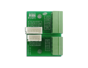


A 48v split phase inverter converts energy from a nominal 48V battery system into split-phase AC power, typically 120/240V for North American-style electrical distribution. In solar PV and storage projects, it can supply both 120V loads such as lighting, office circuits, routers, refrigeration controls, and security systems, as well as 240V loads such as pumps, compressors, workshop equipment, and some HVAC equipment.
For EPCs, installers, resellers, and commercial project owners, the practical question is not simply whether the inverter can produce 120/240V power. The more important question is whether the system architecture is appropriate for the site’s load profile, battery bank, code environment, interconnection requirements, service capability, and long-term economics.
A 48V battery inverter can be highly effective in small commercial, agricultural, telecom, remote facility, and backup power applications. However, it is not a universal solution for every commercial PV project. Because 48V systems operate at relatively low DC voltage, current becomes high as power increases. That affects cable sizing, DC protection, heat management, voltage drop, installation quality, and scalability. For larger C&I facilities, higher-voltage battery systems and three-phase power conversion equipment may be more suitable.
This guide explains where a 48v split phase inverter fits in professional PV projects, how to compare technical specifications, how to size the inverter and battery system, what integration risks to manage, and how procurement teams can evaluate suppliers for repeatable commercial deployment.
A 48v split phase inverter is most relevant where the project requires battery-based backup, off-grid operation, or hybrid solar-plus-storage in a 120/240V split-phase electrical environment. In practice, that usually means distributed energy systems rather than large utility-scale or mainstream three-phase C&I plants.
In North American-style split-phase systems, the AC output includes two 120V legs with 240V available line-to-line. This makes the inverter useful for sites that have a mix of standard branch circuits and moderate 240V equipment. Small businesses, farms, workshops, rural clinics, telecom shelters, remote offices, water pumping stations, and service buildings are typical examples.
For professional projects, the inverter should be evaluated as part of a complete energy system. Its performance depends on battery capacity, battery discharge current, PV charging architecture, AC distribution, generator integration, site temperature, monitoring, and protection design. A good inverter selection cannot compensate for poor load assessment or undersized battery wiring.
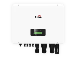
In practical PV system design, “48V split-phase inverter” can refer to several equipment types. These include standalone battery inverters, inverter/chargers, hybrid inverters with integrated MPPT charge controllers, and grid-interactive battery inverters.
EPCs should confirm which functions are integrated into the selected product, because PV charging, grid export capability, generator charging, and automatic transfer switching are not always included in a single unit.
In PV projects, a 48V battery inverter converts stored DC energy from a 48V battery bank into usable AC power through an energy storage inverter system, especially in backup and off-grid configurations. When configured as a split-phase inversor solar, it supplies 120/240V AC to loads through a distribution panel or critical-load subpanel. Depending on the model and system design, it may also charge the battery from PV, the grid, or a generator.
The most common operating role is backup power. For example, a small retail building may use solar and batteries to keep refrigeration, lighting, payment systems, internet equipment, and security circuits running during grid outages. A farm workshop may use a 120/240V inverter for controls, lights, water pumps, and selected tools. A telecom shelter may use a 48V battery plant as the core energy storage system while the inverter supplies AC loads that are not native DC.
In off-grid PV systems, the inverter becomes the primary AC power source. In hybrid systems, it may operate normally with the grid but disconnect and form a local AC supply when the utility fails. In self-consumption applications, the inverter helps shift solar energy into evening or peak-tariff periods, although project economics depend heavily on tariff structure and control capability.
A 48v split phase inverter is most appropriate when the system power level is moderate and the site can be clearly divided into essential and nonessential loads. This is why critical-load backup is often a better fit than whole-building backup. A project that only needs to support IT equipment, emergency lighting, POS terminals, refrigeration controls, gate motors, and a small pump can be designed efficiently. A project that attempts to back up all HVAC, large compressors, EV chargers, production machinery, and kitchen equipment may quickly exceed the practical limits of 48V architecture.
For off-grid projects, the inverter must be sized not only for peak load but also for poor solar periods. Battery autonomy, generator support, and load management become central to design. For hybrid projects, the focus shifts toward transfer behavior, anti-islanding, grid charging permissions, export limits, and utility approval.
Self-consumption and peak shaving are possible at smaller sites, but they require careful financial analysis. Self-consumption requires a grid-interactive inverter or approved control architecture. Off-grid inverter/chargers that can support backup loads are not necessarily approved for grid-parallel operation or export control.
If the inverter lacks advanced energy management, demand control, or export limitation, the savings may be lower than expected. The project team should define the operating objective before selecting equipment: backup resilience, diesel displacement, grid independence, peak reduction, or solar utilization.
The main limitation of 48V architecture is current. In higher power applications, this becomes the primary design constraint rather than voltage itself.
At 10kW output, a 48V battery system may exceed 200A DC current, while a 400V-class battery system may operate around 25A before conversion losses. This difference directly affects cable sizing, heat generation, protection device selection, and overall system scalability.
Example: 6,000W ÷ 0.92 ÷ 44V ≈ 148A
Evaluation triggers for higher-voltage storage systems typically include continuous power above roughly 10–15kW, long DC cable runs, three-phase load dominance, expected system expansion beyond a single cabinet, or AHJ requirements for listed ESS combinations that are not available in 48V configurations.
At 6kW, a 48V inverter typically draws around 125A before losses and 130A or more under real operating conditions. At 10kW, DC current can exceed 200A, making conductor sizing, busbar design, breaker selection, and thermal management major design constraints.
Designers should avoid relying only on nominal voltage assumptions when evaluating conductor sizing and protection devices.
Approximate DC current at nominal 48V highlights how quickly current rises as system power increases:
| AC output power | Approximate DC current before losses | Implicaciones prácticas |
|---|---|---|
| 3 kW | 63 A | Manageable with proper DC protection and short cable runs |
| 5 kW | 104 A | Cable sizing and battery discharge rating become important |
| 8 kW | 167 A | Busbars, breakers, torque control, and ventilation are critical |
| 10 kW | 208 A | BOS cost and voltage drop may become significant |
| 15 kW | 313 A | Often better evaluated against higher-voltage architectures |
These values are simplified and should not replace engineered calculations. They show why 48V systems can become difficult to scale. Large commercial and industrial PV-plus-storage projects often use higher-voltage battery systems because they reduce current, copper requirements, and losses. Three-phase loads may also require dedicated three-phase inverters or commercial power conversion systems rather than split-phase equipment.
The key point for EPCs is to avoid applying residential-style equipment to commercial loads without a full current, surge, compliance, and serviceability review.
Yes, a 48V split-phase inverter can be suitable for commercial solar projects, but mainly for small commercial, rural, remote, agricultural, telecom, and critical-load applications. It is usually not the first choice for large three-phase facilities, high-power manufacturing loads, or scalable C&I storage plants.
Suitability depends on several site-specific factors: total continuous load, largest motor-starting load, 120V leg balance, 240V load requirements, backup duration, battery discharge capability, generator strategy, grid interconnection rules, enclosure environment, and maintenance model. If the system can be designed around defined critical loads and moderate power, a 48V solution can be cost-effective and serviceable. If the project requires high power, long cable runs, complex three-phase distribution, or future expansion to tens or hundreds of kilowatts, a different architecture may reduce lifecycle risk.
Specification comparison should go beyond headline wattage. Many procurement errors happen because buyers compare inverter price and rated output while overlooking surge duration, thermal derating, battery current, AC leg imbalance, enclosure rating, communications, and certification scope.
For commercial PV projects, the inverter datasheet should be read together with the installation manual, approved battery list, wiring diagrams, warranty terms, grid compliance documentation, and monitoring platform documentation. If these documents are incomplete, the project team should treat that as a procurement risk.
Product comparison checklist:
| Especificaciones | Qué hay que comprobar |
|---|---|
| Continuous AC output | Sustained power under real operating temperature |
| Surge rating | Magnitude and duration of motor starting capability |
| L1/L2 capacity | Per-leg output limits under 120V load conditions |
| Battery voltage range | Compatibility with 48V / 51.2V LiFePO4 systems |
| Max DC current | Battery discharge current limit under full load |
| PV input voltage | MPPT maximum and cold-weather Voc margin |
| Transfer rating | Grid-to-off-grid switching behavior and delay |
| Grid certification | UL 1741 / IEEE 1547 or local equivalent compliance |
| Battery protocol | CAN / RS485 compatibility and closed-loop control |
| Enclosure rating | IP rating and environmental suitability |
| Monitoring system | Remote visibility, alarms, and data logging |
| Condiciones de la garantía | Coverage scope, exclusions, and commercial use conditions |
Continuous output power defines how much load the inverter can supply under specified conditions. However, commercial sites often include motors and inductive loads that require starting current much higher than running current. Pumps, compressors, refrigeration equipment, gate motors, HVAC blowers, and shop tools can create short but demanding surges.
A 120/240V inverter for solar systems should be evaluated by both surge magnitude and surge duration. A claim of “2x surge” is not enough unless the datasheet states whether that rating applies for milliseconds, seconds, or a full motor-starting event. Installers should also review overload behavior. Some inverters shut down quickly when overloaded, while others tolerate temporary overload and recover automatically. For a commercial site, nuisance trips can be more damaging than a slightly higher CAPEX.
The load study should identify the largest single starting event and the realistic simultaneous load. If a well pump and refrigeration compressor may start while lighting, IT, and office circuits are already operating, the inverter must handle that combined condition. Where surge is uncertain, soft starters, variable-frequency drives, staged controls, or load-shedding relays may be more economical than oversizing the entire system.
A split-phase inverter supplies two 120V legs and can support 240V line-to-line loads. In a commercial subpanel, the distribution of 120V loads across the two legs matters. Severe imbalance can cause voltage instability, overheating, neutral current issues, or reduced usable inverter capacity depending on inverter design.
Professional design should identify which loads are 120V and which are 240V. Office outlets, network equipment, small refrigeration controls, lighting, alarms, and POS systems may all be 120V. Pumps, compressors, and some HVAC or shop loads may be 240V. The critical-load panel should be arranged so that 120V loads are reasonably balanced across both legs, while 240V loads are checked for surge and running current.
Neutral design is also important. In grid-connected backup systems, neutral-ground bonding must coordinate with the service equipment and transfer method. In off-grid systems, the inverter may be part of a separately derived system, which changes bonding requirements. Mistakes in this area can lead to nuisance trips, inspection failures, unsafe touch voltage, or improper ground-fault behavior.
For system design, 120V loads should be explicitly listed as L1-N and L2-N circuits in the panel schedule. This separation is necessary to understand real-time phase loading instead of only reviewing total kW.
If most 120V loads are concentrated on a single leg, that leg may reach overload while the inverter still shows available total capacity. This can result in voltage imbalance, neutral overheating, and early inverter derating or shutdown depending on internal protection logic.
If an 8kW inverter is rated for 120/240V split-phase output, it may not support 8kW of 120V load on only one leg. EPCs should verify the maximum allowable L1-N and L2-N output separately, not just the total 240V rating.
Leg imbalance should be identified directly from the panel schedule by summing connected loads per breaker position. Circuits should be reviewed under expected simultaneous operation, not only nameplate ratings.
Split-phase load verification table:
| Check item | Por qué es importante |
|---|---|
| Max L1-N output | Prevents overload on one 120V leg |
| Max L2-N output | Ensures balanced inverter utilization |
| 240V load surge | Determines motor start capability |
| Neutral current | Avoids overheating and nuisance trips |
| Panel schedule balance | Improves system stability and efficiency |
A nominal 48V battery system does not operate at exactly 48V. 16-cell LiFePO4 battery systems are often marketed as “48V batteries,” but they are commonly 51.2V nominal systems. This difference affects inverter compatibility and charging behavior.
Typical full-charge voltage ranges are around 56V to 58.4V depending on battery configuration, chemistry, and BMS settings.
Low-voltage cutoff points typically range from around 40V to 44V depending on inverter configuration, discharge limits, and battery protection logic. These voltage windows must be matched carefully with inverter operating ranges to avoid premature shutdown or reduced usable capacity.
Actual voltage varies by chemistry, state of charge, temperature, charge stage, and BMS limits. Lithium iron phosphate battery banks often operate across a different voltage window than lead-acid banks. The inverter must support the battery’s operating range and charge profile.
The DC side deserves special attention because current is high. Cable gauge, fuse rating, breaker interrupt capacity, busbar ampacity, terminal torque, battery rack layout, and disconnect placement all affect safety and reliability. Low voltage does not mean low risk. A 48V battery bank can deliver very high fault current, especially with multiple lithium batteries in parallel.
Voltage drop should be kept low through short DC runs, properly sized conductors, quality terminations, and suitable busbars. Long battery cable routes are usually a poor fit for high-current 48V systems. If the battery room or cabinet must be far from the inverter, the project should reconsider layout or evaluate higher-voltage storage.
Peak inverter efficiency is useful, but commercial systems rarely operate at peak conditions all the time. Partial-load efficiency and idle consumption can materially affect off-grid and backup systems, especially where overnight loads are small. An inverter with high standby consumption may drain the battery faster than expected when supporting only communications, controls, and security circuits.
Thermal derating is another critical specification. Environmental and enclosure design also affect real-world inverter performance. Installations may require NEMA 3R, NEMA 4, or NEMA 4X enclosures depending on outdoor exposure, rain protection, or corrosive environments.
IP-rated enclosures should be selected based on dust and moisture conditions. Corrosion exposure, rodent or insect intrusion, condensation risk, and altitude derating all impact system reliability.
Additional considerations include audible noise from cooling fans, fan serviceability, minimum clearance for airflow, and long-term ventilation stability in enclosed or containerized installations.
Inverters installed in hot mechanical rooms, outdoor enclosures, shipping containers, telecom shelters, or agricultural buildings may not deliver full rated power continuously. EPCs should review derating curves, operating temperature range, ventilation clearance, fan serviceability, enclosure rating, and dust exposure. In hot climates, oversizing the inverter or using multiple units at lower loading may improve reliability.
Sizing a 48v split phase inverter system begins with loads, not with PV module capacity or inverter price. A common project mistake is to ask, “What size inverter should we buy?” before defining which loads must run, for how long, under what outage condition, and with what acceptable load-shedding strategy.
A structured sizing process helps reduce oversizing, undervaluing surge demand, and battery current stress in 48V systems. The following steps are commonly used in commercial PV design workflows.
Add up all essential running loads in kW. This includes lighting, IT systems, refrigeration controls, pumps, and other critical circuits that must operate at the same time. The result defines the minimum continuous inverter rating.
Identify the largest motor or inductive load starting at any time. Compare it with the inverter surge rating and duration. Pumps, compressors, and HVAC equipment usually define this requirement.
Check how 120V loads are distributed across both inverter legs. Large imbalance can reduce usable capacity and increase neutral current. A balanced design improves stability and reduces thermal stress.
Battery current ≈ AC load ÷ inverter efficiency ÷ battery voltage
Por ejemplo:
6,000W ÷ 0.92 ÷ 48V ≈ 136A
This step confirms whether the battery system can safely support peak discharge without BMS trips or cable overheating.
Required battery kWh ≈ load kW × runtime hours ÷ usable DoD ÷ inverter efficiency
This calculation defines total storage capacity for the required backup duration. Both depth of discharge and inverter losses must be included.
At 240V split-phase output, typical current levels are:
These values help evaluate breaker sizing, conductor selection, and panel design.
Add a safety margin for temperature, cable losses, and future load expansion. A common design practice is 10–25% headroom depending on site conditions.
Check whether PV and generator input can restore battery state of charge within the required time window. Off-grid systems should ensure recovery after low-sun or outage events to avoid progressive discharge cycles.
Professional load assessment separates essential loads from convenience loads and production loads. A small commercial facility may have lighting, routers, security cameras, fire alarm panels, POS systems, refrigerators, office equipment, water pumps, roll-up doors, and HVAC. Not all of these need to operate during an outage.
Critical-load prioritization can reduce CAPEX substantially. For example, backing up an entire building may require a much larger inverter, more battery capacity, larger conductors, and more complex transfer equipment. Backing up a dedicated subpanel for refrigeration, IT, security, emergency lighting, and controls may achieve the business objective at a fraction of the installed cost.
The load assessment should consider both power and energy. Power, measured in kW, determines inverter size and battery discharge capability. Energy, measured in kWh, determines backup duration. A 2kW critical load for 10 hours requires a very different battery system than an 8kW load for 30 minutes, even if both use the same nominal battery voltage.
The number of batteries depends on required energy capacity, allowable depth of discharge, battery chemistry, battery current rating, expected backup duration, and inverter power. Nominal voltage alone does not determine battery count.
For example, suppose a site needs to support 4kW of critical loads for 6 hours. The AC energy requirement is 24kWh. After allowing for inverter losses, battery reserve, and operational margin, the required nominal battery capacity may be closer to 30kWh or more. If the selected 48V battery module provides 5kWh nominal capacity, the project may need at least six modules, subject to discharge-current limits and manufacturer parallel rules.
Battery power capability is just as important as energy. A battery bank may have enough kWh for the backup duration but insufficient discharge current to support the inverter at full output. This is particularly relevant for lithium batteries with BMS current limits and for lead-acid batteries whose usable capacity declines at high discharge rates.
In a DC-coupled system, PV energy charges the 48V battery through an MPPT charge controller or through an integrated hybrid inverter. The PV string voltage may be much higher than the battery voltage, but the charging stage must be compatible with the battery bank’s voltage and current limits.
PV array sizing should account for daily load energy, seasonal solar resource, battery recharge time, charge controller current limit, battery maximum charge current, and generator backup strategy. Additional design checks should include MPPT maximum input voltage, MPPT operating voltage window, maximum PV input current, maximum PV charging current to battery, cold-weather Voc correction, PV array oversizing ratio, number of MPPT trackers, and grounding or rapid shutdown requirements depending on jurisdiction.
If an integrated inverter has a 500Vdc PV input limit, EPCs must calculate cold-weather open-circuit voltage to ensure the string does not exceed the MPPT maximum on the coldest expected site temperature.
Oversizing the PV array without sufficient charge capacity may not improve performance. Conversely, undersizing PV can leave an off-grid system dependent on generators during cloudy periods.
For remote sites, charging reliability is often more important than maximum annual yield. A system that recovers battery state of charge quickly after an outage or cloudy day may provide better operational value than a system optimized only for lowest upfront cost.
Both AC-coupled and DC-coupled architectures can use a inversor solar híbrido with battery backup, but they behave differently.
| Arquitectura | La mejor opción | Key advantage | Main caution |
|---|---|---|---|
| DC-coupled PV + 48V battery | Off-grid, backup, new installations | Efficient battery charging and simpler islanded operation | PV charge limits and battery compatibility must be verified |
| AC-coupled PV + battery inverter | Retrofits with existing PV inverters | Easier to add storage to an existing AC system | Backup behavior, frequency shifting, and export control can be complex |
| Hybrid inverter with integrated MPPT | Small commercial and distributed systems | Compact design and simplified commissioning | Less flexible if PV or battery requirements exceed internal limits |
| Separate inverter/charger plus external MPPT | Remote, modular, serviceable systems | Flexible expansion and replacement | More engineering and commissioning work |
AC-coupling can be attractive for retrofit projects because existing PV inverters may remain in place. During an outage, the battery inverter must form the local AC grid. The existing PV inverter must recognize that grid, operate within its voltage and frequency limits, and reduce output when batteries reach full charge. If these control interactions are not compatible, the PV inverter may trip offline or continue producing power in an unstable manner. However, when the grid is down, the battery inverter must form the AC reference and control PV production. Not all combinations behave well in islanded mode. DC-coupling is often more predictable for off-grid and backup systems, but it requires careful PV string and charge controller design.
Compliance is a project requirement, not an optional product feature. Modern distributed energy projects typically follow structured approval and interconnection workflows defined in frameworks such as the U.S. DOE interconnection checklist, which outlines how utility coordination, safety review, and system verification are integrated into project development. A 48v split phase inverter used in a grid-interactive system must meet applicable safety and interconnection requirements for the jurisdiction.
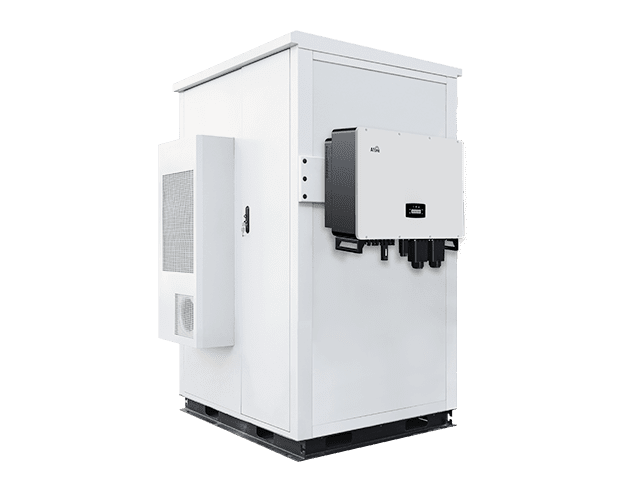
In energy storage and hybrid PV systems, compliance may extend beyond inverter certification alone. Equipment may also be evaluated under UL 1973 for battery safety, UL 9540 for energy storage system certification, and UL 9540A for system-level thermal runaway testing. Fire and installation requirements for commercial storage systems are often referenced through NFPA 855, especially in containerized or indoor battery installations.
Electrical design and interconnection requirements may additionally fall under NEC Article 690 for PV systems, NEC Article 705 for grid interconnection, NEC Article 706 for energy storage systems, NEC Article 702 for optional standby systems, and NEC Article 710 for stand-alone power systems. Inverter performance and grid support behavior are commonly assessed under UL 1741 SB.
In North America, project teams commonly encounter UL 1741, IEEE 1547, National Electrical Code requirements, utility interconnection rules, and local AHJ expectations.
For global B2B readers, it is also important to recognize that split-phase 120/240V is not the standard commercial distribution format in many regions. In much of Europe, for example, commercial PV systems commonly connect to 230/400V three-phase networks. In those markets, 48V inverters may still be relevant for off-grid telecom, rail, remote, or DC plant applications, but they are less common for mainstream grid-tied C&I PV.
IEEE 1547 establishes interconnection and interoperability requirements for distributed energy resources in the United States, including grid support functions such as voltage and frequency ride-through. UL 1741 is commonly used for inverter safety and grid-interactive certification. NEC requirements affect PV circuits, energy storage systems, disconnects, conductor ampacity, labeling, working clearances, and rapid shutdown where applicable.
The AHJ and utility have final authority. EPCs should confirm local requirements before procurement, especially for zero-export systems, non-export backup systems, and systems using generator integration.
Depending on system design, isolation may be handled by an internal transfer relay, external automatic transfer switch, microgrid interconnection device, or dedicated backup panel arrangement.
For commercial sites, transfer performance should be tested under realistic load. Some loads tolerate a brief interruption; others may require UPS-level continuity. If server racks, payment systems, medical devices, or control systems are involved, the transfer time and power quality should be verified before handover.
Many commercial sites face export limitations. Net metering may be unavailable, interconnection capacity may be restricted, or the utility may require export control. The inverter and monitoring platform should support the required operating mode with verifiable settings.
Zero-export systems require accurate metering and fast control response. Commissioning should include proof that the system behaves correctly during load changes, battery charging, PV production changes, and grid restoration. If export control is required by the utility, documentation should show meter placement, control logic, inverter settings, and test results.
Permit approval depends on documentation completeness, including single-line diagrams, equipment datasheets, protection design, labeling, grounding, and commissioning records. Clear and consistent documentation reduces review delays and improves installation consistency across sites.
Battery compatibility is one of the most important success factors in 48V inverter projects. The inverter and battery must agree on voltage range, charge limits, discharge limits, temperature behavior, communication protocol, and fault response.
Lead-acid batteries have long been used in 48V systems, especially in telecom and off-grid applications.
Lead-acid 48V banks also have different absorption, float, and equalization charging requirements compared to lithium systems. These parameters must be configured correctly to avoid undercharging, sulfation, or reduced battery lifespan.
The inverter’s low-voltage disconnect, charge voltage, float voltage, and reconnect voltage must be matched to the battery manufacturer’s limits. Incorrect settings can cause premature BMS trips or chronic undercharging.
They are familiar, widely available, and tolerant of some operating conditions. However, they require maintenance, ventilation considerations, and conservative depth of discharge if long life is expected.
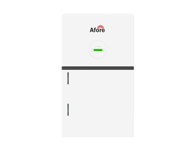
Lithium iron phosphate, or LiFePO4, has become increasingly common in professional 48V systems because it offers higher usable capacity, longer cycle life, lower maintenance, and better efficiency. However, lithium batteries rely on a battery management system. The BMS may disconnect the battery under low voltage, high voltage, overcurrent, or temperature faults. If the inverter is not configured correctly, a BMS trip can shut down the site unexpectedly.
For commercial systems, battery selection should consider usable kWh, continuous and peak discharge current, charge current, operating temperature, enclosure rating, fire and installation requirements, communication compatibility, warranty conditions, and expansion rules.
Closed-loop communication allows the battery BMS and inverter to exchange state of charge, voltage limits, current limits, temperature status, and alarms. Common physical layers include CAN and RS485, but protocol details are often manufacturer-specific.
Closed-loop control can improve charging accuracy and reduce the risk of overcharge, deep discharge, or incorrect state-of-charge reporting. It may also be required for warranty compliance. However, compatibility should not be assumed. Project teams should verify that the exact inverter firmware version and battery model are approved to work together.
Open-loop operation, based on voltage and current settings, may be acceptable in some systems, especially with lead-acid batteries or carefully configured lithium systems. But for commercial sites with critical loads, closed-loop communication is usually preferable because it gives the inverter better information about battery limits and fault conditions.
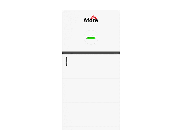
Parallel battery expansion is common in 48V systems, but it must be engineered. Unequal cable lengths, poor busbar design, different battery ages, inconsistent state of charge, and mixed battery models can cause uneven current sharing. Over time, one battery string may work harder than others, reducing life and increasing fault risk.
Before promising future expansion, integrators should confirm the maximum number of parallel batteries, required communication topology, breaker requirements, cable sizing, and firmware rules. Adding batteries later may require matching battery versions, updating firmware, reconfiguring the inverter, or replacing busbars and protection devices.
Generators remain important in many off-grid and backup applications. A 48v split phase inverter with generator support can charge batteries, pass AC power to loads, and start or stop the generator based on state of charge, load, or schedule.
Generator sizing should account for battery charging load and site load at the same time. Commissioning checks should include two-wire start compatibility, generator warm-up and cool-down settings, AC input current limit configuration, battery charging current limit, frequency and voltage tolerance, neutral bonding compatibility, manual bypass planning, and testing under combined load and charging conditions.
Commissioning should include a test where the generator supports both site load and battery charging at the configured AC input current limit. This confirms the inverter does not overload or reject the generator under realistic conditions.
If the inverter can charge batteries at 4kW while the site load is 5kW, the generator may need to supply 9kW plus margin. The arithmetic load sum is only a starting point. Generator sizing should also consider power factor, motor starting surge, site altitude, ambient temperature, fuel type, and the inverter’s AC input current limit. Poor coordination can overload the generator, create unstable voltage, or cause repeated transfer failures.
For remote sites, fuel logistics may be a major cost driver. A well-designed PV-battery-generator system can reduce generator run hours, but it should also preserve generator health by avoiding excessive short cycling and very light loading.
A 48V system can appear simple because the nominal battery voltage is low. In professional installations, that assumption is dangerous. High current, battery fault energy, split-phase bonding, and grid-transfer requirements all require disciplined installation and commissioning.

DC wiring should be designed for ampacity, voltage drop, temperature, bundling, terminal ratings, and fault interruption. Protective devices must be suitable for DC use and rated for the available fault current. Battery disconnects should be accessible and clearly labeled. Cable lugs should be properly crimped, terminals torqued to specification, and conductors protected from abrasion.
A practical commissioning process should verify at least the following steps:
These steps are not a substitute for local code inspection, but they reduce field failures and callbacks.
Grounding and bonding errors are among the most common causes of nuisance trips and inspection issues in split-phase inverter systems. The project design should define whether the inverter output is bonded, where the neutral-ground bond exists, whether neutral switching is required, and how equipment grounding conductors are routed.
Critical-load subpanels should be clearly labeled and configured so backed-up circuits are separated from non-backed-up loads. If the inverter cannot support certain large loads, those circuits should not be present in the backup panel. This avoids accidental overload during outages.
Reliability problems often come from predictable installation errors: undersized DC cables, excessive battery cable length, poor ventilation, incompatible batteries, weak communications wiring, incorrect breaker types, unbalanced 120V loads, insufficient surge capacity, poor labeling, and lack of operator training.
Monitoring setup is also frequently underestimated. A system that cannot be monitored remotely is harder to troubleshoot, especially for resellers and EPCs managing multiple sites. Weak Wi-Fi, missing cellular backup, incomplete user permissions, or unconfigured alarms can turn a manageable issue into a service visit.
For commercial users, the value of a solar inverter with battery backup depends on whether it works when needed. O&M planning should begin during design, not after the first fault.
Remote monitoring should show inverter status, battery state of charge, PV production, load consumption, grid status, generator status, fault alerts, and historical performance. For fleet operators, the platform should allow multiple sites to be viewed consistently.
The best monitoring data supports action. For example, repeated overload warnings may indicate that the site has added loads after commissioning. Battery imbalance or communication errors may indicate wiring or firmware issues. High internal temperatures may show that ventilation needs improvement.
Maintenance intervals depend on site conditions and equipment type. Dusty workshops, farms, and telecom shelters may require more frequent inspection than clean indoor electrical rooms. Fans, filters, terminals, cable insulation, enclosure seals, firmware, battery health, and event logs should be reviewed periodically.
Lead-acid systems may require electrolyte checks, equalization planning, corrosion inspection, and ventilation review. Lithium systems require less routine maintenance but should still be checked for communication status, temperature events, capacity degradation, and BMS alarms.
Procurement teams should review warranty duration, exclusions, commercial-use conditions, RMA process, regional support, replacement lead times, firmware support, and installer training. A low-cost inverter may become expensive if a failure causes downtime and replacement units are unavailable.
For multi-site projects, spare parts strategy matters. Standardizing on a limited number of inverter, battery, breaker, and monitoring components can reduce training requirements and service complexity. It also makes it easier to stock replacement parts.
Common operational risks include battery communication loss, inverter overload, thermal shutdown, transfer failure, contactor faults, generator start failure, and reduced battery capacity over time. Critical sites should have alarm escalation procedures. If refrigeration, security, telecom, or safety systems depend on the inverter, someone must be responsible for responding to alarms.
Redundancy may be justified where downtime is costly. In some cases, this means multiple inverters. In others, it means generator backup, load shedding, spare battery modules, or a bypass arrangement that allows service without shutting down all critical loads.
The inverter is only one part of installed system cost. A realistic budget includes batteries, PV modules, racking, charge controllers or hybrid inverter hardware, wiring, busbars, breakers, disconnects, transfer equipment, monitoring, permits, engineering, labor, commissioning, training, and maintenance.
In 48V systems, balance-of-system cost can rise quickly at higher power because of high DC current. Large conductors, DC-rated breakers, battery cabinets, busbars, and labor for terminations can materially affect CAPEX. Oversizing the inverter without clear load justification may also require a larger battery bank and larger protection equipment.
Battery capacity is usually the largest cost driver in backup systems. A project designed for 24 hours of autonomy will cost much more than one designed for 4 hours, even if both use the same inverter. Load segmentation is therefore one of the most powerful cost-control tools.
ROI depends on project objective. Backup-focused projects often justify investment through avoided downtime, protected inventory, business continuity, reduced generator fuel use, and resilience value. These benefits may not appear in a simple energy-savings payback calculation.
Self-consumption and peak shaving depend on tariff structure. If the site has high demand charges or time-of-use rates, storage may create measurable savings. If electricity is inexpensive and outages are rare, the financial case may rely more on resilience than energy arbitrage.
A 48v split phase inverter should be compared against alternatives: generator-only backup, high-voltage hybrid storage, three-phase commercial inverters, AC-coupled battery systems, or a smaller critical-load UPS approach. Lifecycle comparison should include efficiency losses, battery replacement, maintenance, service response, expansion needs, and downtime risk.
For moderate split-phase loads, 48V systems can be practical and cost-effective. For larger power levels or long-term expansion, higher-voltage systems may reduce conductor cost and improve scalability even if the initial equipment price is higher.
Resellers should position 48V split-phase products around well-defined use cases: small commercial backup, agricultural loads, remote power, telecom shelters, workshops, rural facilities, and hybrid PV-storage systems with moderate power requirements. Overselling into large C&I applications can create support problems and damage customer trust.
A professional channel strategy should include compatibility lists, standard wiring packages, approved battery configurations, training materials, commissioning forms, and clear escalation paths for technical support. The product should be sold as a system package, not as an isolated inverter.
Procurement should verify both product-level and system-level suitability. A datasheet may show attractive power ratings, but the project may still fail if the inverter lacks local certification, battery compatibility, generator support, or after-sales service.
Procurement teams should verify certified listings, grid-interactive approval where required, surge ratings with duration, AC output configuration, DC input range, enclosure rating, operating temperature, derating curves, communications, monitoring, warranty terms, and installation documentation.
A complete documentation package remains a key bankability indicator. Gaps in manuals, unclear specifications, unsupported battery compatibility, or limited service coverage increase project risk in commercial deployments.
System-level certification scope should be checked where ESS approval is required. In some jurisdictions, inverter and battery components must be validated as an integrated system rather than independent listings.
System-level procurement checks PV voltage windows, MPPT limits, battery communication protocols, generator input requirements, AC transfer ratings, export-control capability, and monitoring access. If the site uses an energy management system, the inverter should support practical data integration through appropriate communication interfaces.
Firmware support should also be considered. Grid codes, battery protocols, and monitoring platforms evolve. A supplier that cannot provide firmware updates or technical bulletins may create long-term risk.
For EPCs and resellers deploying across multiple facilities, logistics can be as important as electrical performance. Lead times, regional inventory, replacement units, support response, installer training, and documentation quality affect project delivery and O&M cost.
Standardization helps. A repeatable inverter-battery package can reduce design time, installation errors, training effort, and spare parts complexity. However, standardization should include a clear threshold for when the project must move to a higher-voltage or three-phase platform.
A 48v split phase inverter can be a strong solution when the project has moderate 120/240V loads, clear backup priorities, manageable battery current, and a defined service model. It is especially useful for small commercial buildings, farms, remote facilities, telecom sites, workshops, and critical-load solar-plus-storage systems.
The safest procurement approach is to start with the site load profile, required backup duration, battery architecture, code requirements, and O&M plan. If those factors align with the limits of 48V architecture, the system can be reliable and economical. If they do not, moving to a higher-voltage or three-phase platform early in design will usually reduce lifecycle risk.
A 48V split phase inverter converts DC from a 48V battery into 120/240V AC power. Split phase means two 120V legs with 240V between them. Most systems use battery storage, and PV input is only used if the inverter has built-in charging. It is commonly used for backup and off-grid power systems.
Yes, for small commercial and critical-load systems. It works best when total power is moderate and loads are clearly defined. The main limitation is high DC current at higher kW levels. Larger commercial sites often move to higher-voltage or three-phase systems.
Battery size depends on energy and runtime requirements. A 4kW load for 6 hours needs about 24kWh of AC energy. After losses, this may require around 30kWh of battery capacity. If each module is 5kWh, about six batteries may be needed if discharge current is sufficient.
Many inverter/chargers can work with generators. Not all models support auto-start or generator input. The generator can supply loads and charge batteries at the same time. Proper sizing must consider both load and charging demand.
At 10kW, a 48V system can exceed 200A DC current before losses. Higher-voltage systems operate at much lower current for the same power. Lower current reduces cable size, heat, voltage drop, and protection complexity. It also improves scalability and lifecycle cost in larger systems.
https://standards.ieee.org/ieee/1547/5915
https://www.energy.gov/cmei/femp/articles/distributed-energy-interconnection-checklist