





A solar power charge controller regulates how energy from PV modules charges a battery bank. In practical terms, it controls charging voltage and current. This ensures efficient battery charging and protection against overcharging, deep discharge, reverse current, voltage instability, and unsafe operating conditions. For commercial and industrial PV projects, this is not a minor accessory. It is a project-critical power electronics component that can affect battery life, system uptime, commissioning risk, warranty compliance, and long-term operating cost.
This guide is written for EPCs, PV installers, system integrators, distributors, resellers, facility managers, and commercial asset owners evaluating solar power charge controllers. It also covers systems where charging control is integrated into hybrid inverters, inverter-chargers, or battery energy storage systems (BESS), not only standalone devices. It focuses on professional selection logic rather than consumer product rankings. The goal is to help project teams specify the right controller, avoid common design errors, and assess the component as part of the full PV-plus-storage system.
A solar power charge controller is installed between the PV array and the battery bank in DC-coupled systems. Its main function is to regulate the battery charging process by controlling voltage and current.
Without proper charge regulation, batteries may be overcharged, undercharged, overheated, or deeply discharged. These conditions reduce service life and increase operational risk.
In commercial projects, this matters because batteries are often among the highest-value assets in the system. A controller that is undersized, incorrectly configured, or incompatible with the battery chemistry can trigger premature battery degradation, repeated service visits, and customer dissatisfaction. For remote sites, even a small configuration error can result in expensive truck rolls and extended downtime.
A battery charge controller for solar manages the transition between variable PV output and the controlled charging requirements of the battery bank. PV modules do not produce a fixed voltage or current. Their output changes with irradiance, temperature, shading, and operating voltage. Batteries, meanwhile, require specific charging behavior depending on chemistry, state of charge, and temperature.
Modern controllers typically provide overcharge protection, low-voltage disconnect for DC loads, reverse current blocking, reverse polarity protection, short-circuit protection, over-temperature protection, and temperature compensation. In lead-acid systems, temperature compensation is particularly important because charging voltage should generally decrease at higher battery temperatures and increase at lower temperatures. In lithium systems, the controller may need to coordinate with the battery management system rather than relying only on fixed voltage thresholds.
The controller also protects the PV array and battery bank from reverse current at night, when battery energy could otherwise flow back toward the solar modules. In professionally designed systems, these functions are supported by external balance-of-system protection such as fuses, breakers, disconnects, surge protection, grounding, and correct conductor sizing.
Grid-tied solar systems without batteries generally do not require a standalone solar power charge controller, because PV energy is processed directly by the inverter through MPPT and grid synchronization functions.
Charge controllers become necessary when battery charging is required on the DC side, including off-grid systems, hybrid systems with external battery banks, telecom power systems, and microgrid applications.
In many modern commercial systems, charging functions may be integrated into hybrid inverters, inverter-chargers, or battery energy storage systems, meaning the controller function still exists but is not always a separate physical device.

In a DC-coupled architecture, PV modules feed the charge controller, and the controller charges the battery bank through a DC bus. The inverter then converts battery DC power into AC power for site loads. DC loads, where present, may also be connected through controlled load terminals or a separate DC distribution system.
In an AC-coupled architecture, PV inverters feed an AC bus, while battery charging and discharging are managed by a battery inverter or hybrid inverter. In this case, the standalone charge controller may not be used, although the battery inverter performs related charging and protection functions.
This distinction is important for design responsibility. In a DC-coupled system, the charge controller is a central design component. It affects string voltage, PV array sizing, battery charge profile, monitoring, and DC protection. In an AC-coupled or integrated hybrid system, those decisions move partly into the inverter and energy storage system specification. EPCs should verify whether the selected inverter includes suitable MPPT inputs, battery charging logic, BMS communication, and grid compliance functions, or whether separate charge controllers are still required.
The decision depends on system architecture and voltage level:
This decision should be made at system architecture level, not at component level.
For EPCs and installers, controller selection affects commissioning speed, system reliability, field service workload, and warranty exposure. A controller that supports the correct battery profile, clear configuration menus, robust monitoring, and reliable fault reporting can reduce startup issues. A controller with poor documentation or limited compatibility can slow commissioning and increase the risk of incorrect settings.
For resellers and distributors, the business case is broader than stocking a low-cost controller with attractive headline ratings. Professional customers need products with consistent quality, regionally appropriate certifications, spare parts availability, technical documentation, and responsive after-sales support. Standardizing on a smaller number of well-supported models can simplify training, inventory, troubleshooting, and repeat project delivery.
The two dominant technologies are PWM and MPPT. Both regulate battery charging, but they do so in fundamentally different ways. For commercial PV projects, the distinction affects energy yield, voltage flexibility, cable design, battery charging behavior, and lifecycle cost.
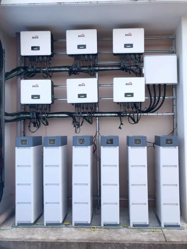
An MPPT solar charge controller uses Maximum Power Point Tracking to operate the PV array near the voltage and current combination where it produces maximum power. It then uses DC-DC conversion to transform the higher PV voltage into the correct battery charging voltage, increasing charging current where conditions allow.
This is especially valuable when the PV array voltage is significantly higher than the battery voltage. It also improves energy harvest in cold weather, when module voltage rises, and during periods when battery voltage is low. In many real-world systems, MPPT controllers can deliver roughly 10–30% more usable energy than PWM controllers, although the actual gain depends on climate, array design, battery state of charge, and load profile.
For professional applications, MPPT is usually the default choice. It allows longer PV strings, reduces current on the array side, can reduce cable losses, and provides greater flexibility when matching modern PV modules to 24 V, 48 V, or higher battery systems. It is particularly suitable for telecom power, remote industrial sites, commercial backup systems, agricultural infrastructure, and hybrid PV-storage projects where energy yield and reliability matter more than the lowest upfront cost.
A PWM charge controller works more like a high-speed electronic switch connecting the PV array directly to the battery. It pulls the array voltage close to battery voltage and regulates charging by rapidly switching current on and off. Because PWM does not convert excess voltage into additional charging current, the PV array nominal voltage must closely match the battery voltage.
PWM controllers are simpler and usually less expensive. They can be appropriate for small, low-cost, non-critical systems where the array and battery voltage are well matched, energy losses are acceptable, and operational consequences of failure are limited. Examples might include small DC lighting systems, basic monitoring points, or legacy low-power installations.
However, PWM is often less attractive in commercial projects. Lower energy harvest can require additional PV capacity, and limited voltage flexibility can increase BOS cost or constrain module selection. In systems where battery life, uptime, and service cost matter, the lower purchase price of PWM may not translate into lower lifecycle cost.
The professional comparison should not stop at device cost. EPCs should compare MPPT and PWM controllers across system-level criteria, including annual energy harvest, PV string flexibility, wiring losses, thermal performance, monitoring capability, battery compatibility, and field service risk.
| Evaluation factor | MPPT controller | PWM controller |
|---|---|---|
| Typical energy harvest | Higher, often 10–30% advantage depending on conditions | Lower when PV voltage exceeds battery voltage |
| PV array voltage flexibility | Haut | Limitée |
| Commercial suitability | Strong for most battery-based PV systems | Mainly small or low-cost systems |
| Cable and BOS optimization | Better with higher array voltage | Less flexible |
| Upfront cost | Plus élevé | Plus bas |
| Lifecycle value | Often stronger where uptime and battery life matter | Acceptable for simple, non-critical loads |
A slightly higher CAPEX for MPPT can be justified if it reduces array oversizing, improves charging reliability, supports future expansion, or avoids service issues. For resellers, MPPT products also tend to align better with professional market demand because modern commercial buyers increasingly expect remote monitoring, lithium compatibility, and flexible PV input design.
MPPT controller datasheets often advertise peak conversion efficiencies in the 95–99% range. These values are useful, but they do not tell the full story. EPCs should review efficiency across the expected voltage range, current range, and ambient operating conditions. A controller that performs well at nominal test conditions may derate significantly in high ambient temperatures or poorly ventilated enclosures.
Thermal design is especially important in telecom cabinets, agricultural equipment rooms, containerized microgrids, rooftop service areas, and desert or tropical environments. Heat accelerates electronic component aging and may trigger output current derating. The enclosure rating, cooling method, fan strategy, heatsink design, installation clearance, and ambient temperature range should all be reviewed during specification.
For critical systems, derating curves are more valuable than peak ratings. A controller rated for high current at 25°C may deliver less current at 45°C or 50°C. If the project is located in a hot climate or inside a sealed enclosure, thermal headroom should be treated as a design requirement, not an afterthought.
Correct sizing is one of the most critical steps in selecting a solar power charge controller. The process must ensure compatibility across PV input voltage, PV input current, battery charging current, and thermal operating limits. These parameters must be evaluated separately because they represent different parts of the energy conversion chain.
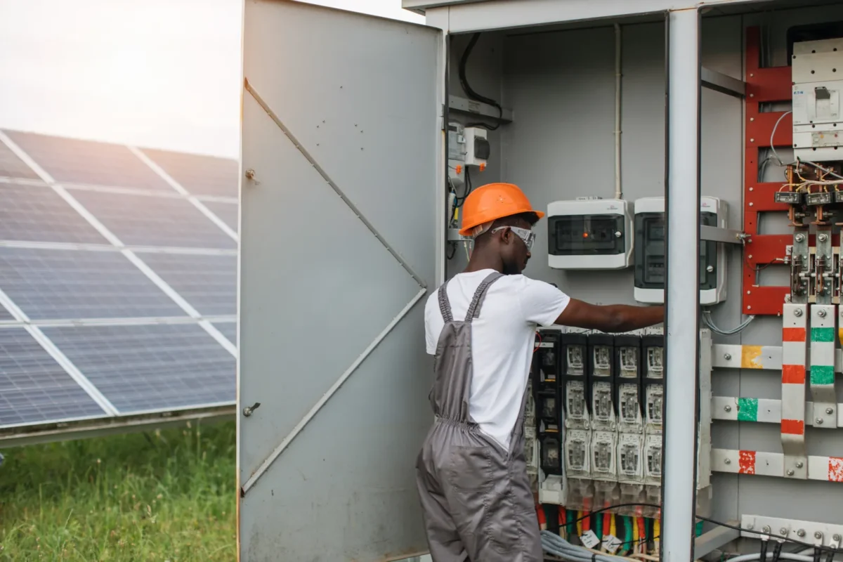
A practical sizing process starts with the battery bank voltage and the PV array design. The controller must support the nominal battery voltage, the maximum charging current, and the PV input voltage under the coldest expected site conditions. It must also handle array current with suitable safety margin.
A simplified professional sizing workflow is shown below.
| Design item | What to verify | Pourquoi c'est important |
|---|---|---|
| Design item | What to verify | Pourquoi c'est important |
| Tension de la batterie | 12 V, 24 V, 48 V, or higher | Determines controller output compatibility |
| PV open-circuit voltage | Cold-temperature adjusted string Voc | Must remain below maximum controller input voltage |
| PV short-circuit current | Array Isc with margin | Prevents overcurrent stress |
| Charge current | PV power divided by battery voltage, adjusted for efficiency | Confirms controller output rating |
| Chimie des batteries | Lead-acid, AGM, gel, LiFePO₄, other lithium | Determines charge profile and BMS needs |
| Installation temperature | Ambient and enclosure conditions | Affects derating and service life |
This table summarizes the key verification items. However, professional design requires separating PV-side constraints, battery-side constraints, and thermal operating limits.
Key point: PV input voltage is a hard safety limit and must be checked under cold-weather Voc conditions, not STC conditions.
Key point: battery charging current is determined by PV power and system voltage, not by PV Isc.
Key point: thermal derating is often the real limiting factor in commercial installations.
Two different sizing rules apply to two different constraints:
(1)PV-side protection rule (input current safety)
Controller input current rating ≥ 1.25 × PV array short-circuit current (Isc)
This is used for input overcurrent protection and electrical safety margin
(2)Battery charging capacity rule (output sizing)
Controller output current ≈ (PV power × efficiency) ÷ battery charging voltage
Où ?
This is used to size charging capability, not PV input safety
System conditions:
(3,600 × 0.95) ÷ 54 ≈ 63.3 A
63.3 × 1.25 ≈ 79.1 A
Final recommendation: 80 A MPPT controller (minimum), 100 A preferred for design margin
PV input voltage is a hard design limit. It must be calculated under coldest expected conditions because PV voltage increases as temperature decreases.
Cold-weather open-circuit voltage can be estimated using:
Voc(cold) = Voc(STC) × [1 + β × (Tcell − 25°C)]
Où ?
Assumptions:
Step calculation:
Result: A 200 V MPPT controller may be exceeded in cold climates, creating a risk of permanent equipment damage.
In professional design, three current values must be treated separately:
These values are NOT interchangeable and must be verified independently.
One controller can handle multiple PV strings if total voltage and current remain within specification.
Typical configuration:
For larger systems, multiple controllers can operate in parallel to improve:
However, parallel systems require:
Correct sizing is not a single calculation. It is a system-level verification process covering:
A properly sized solar power charge controller improves system efficiency, extends battery life, and reduces long-term operational risk in commercial PV applications.
As a general engineering principle:
Controller continuous current rating should be selected with margin above expected array current. Many designers use at least 1.25 × array short-circuit current as a starting point.
At the same time, charging current must be verified using PV power:
Controller output current ≈ (PV power × efficiency) ÷ battery voltage
This separation ensures PV safety and battery sizing are not incorrectly mixed into one rule.
Small systems may use 12 V or 24 V battery banks, but commercial and industrial systems often favor 48 V or higher DC voltages. Higher voltage reduces current for the same power level, which can reduce conductor size, voltage drop, heat, and BOS cost.
In larger commercial or utility-scale storage systems, battery voltages may reach hundreds of volts and charge-control functionality is typically integrated into battery inverters, DC-DC converters, or energy storage system architecture rather than small standalone controllers.
Battery chemistry compatibility must be verified carefully. Lead-acid, AGM, gel, and lithium iron phosphate batteries have different voltage setpoints, charging stages, temperature requirements, and protection logic.
A correctly selected controller cannot compensate for poor BOS design. Cable ampacity, voltage drop, insulation rating, DC disconnects, overcurrent protection, grounding, surge protection, and combiner box design all influence system safety and performance.
PV conductors should be sized for expected current, environmental conditions, routing method, and allowable voltage drop. Battery-side conductors often carry high current and require particular attention to short-circuit protection.
For installers, many field failures are not caused by the controller itself but by loose terminals, undersized conductors, poor crimping, inadequate ventilation, missing overcurrent protection, or incorrect polarity.
Professional installation quality is therefore as important as component selection in determining system reliability.
The controller must be matched not only to the PV array but also to the battery and inverter architecture. This is especially important as commercial projects shift from lead-acid batteries toward lithium systems with active BMS communication.
Lead-acid batteries typically use multi-stage charging: bulk, absorption, float, and sometimes equalization. Bulk charging delivers current until the battery reaches a target voltage. Absorption holds voltage while current tapers. Float maintains the battery at a lower voltage to offset self-discharge. Equalization, where applicable, applies a controlled higher voltage to flooded lead-acid batteries to reduce stratification and balance cells.
AGM and gel batteries usually require more conservative charging profiles and generally should not receive flooded lead-acid equalization unless the battery manufacturer explicitly allows it. Lithium batteries, including LiFePO₄, typically require tighter voltage and current limits and do not use float and equalization in the same way as lead-acid batteries.
| Battery type | Key controller requirements | Common risk |
|---|---|---|
| Battery type | Key controller requirements | Common risk |
| Flooded lead-acid | Bulk, absorption, float, optional equalization, temperature compensation | Underwatering, excessive equalization, poor ventilation |
| AGA | Accurate voltage limits, temperature compensation, no inappropriate equalization | Overvoltage and dry-out |
| Gel | Conservative voltage settings, no equalization unless specified | Permanent damage from overvoltage |
| LiFePO₄ | Precise voltage/current limits, BMS coordination, communication support | Charging outside BMS limits |
| Other lithium | Chemistry-specific profile and BMS integration | Warranty non-compliance |
To properly design battery charging behavior, controllers must be matched not only by chemistry type but also by control method and communication requirements.
The controller settings should be aligned with the battery manufacturer’s published charge parameters. Generic presets are convenient, but they should not replace engineering verification.
Lithium systems usually rely on a Battery Management System to monitor cell voltage, temperature, state of charge, and allowable charge/discharge current. In commercial systems, the controller may need to communicate with the BMS through CAN, RS485, Modbus, dry contacts, or a proprietary protocol.
There are two primary control strategies in lithium battery systems: voltage-based (open-loop) control and BMS-integrated (closed-loop) control. In voltage-based control, the charge controller operates using fixed voltage thresholds without real-time battery feedback. In BMS-integrated control, charging voltage and current are dynamically adjusted based on real-time battery data such as state of charge, temperature, and cell-level protection signals.
This communication is not merely for monitoring. It may be required to dynamically limit charging current, stop charging during high or low temperature events, prevent overvoltage, and coordinate shutdown sequences. Without proper BMS coordination, a controller may continue attempting to charge when the battery has reduced or suspended charge acceptance. That can cause nuisance trips, contactor cycling, fault events, or warranty issues.
In some lithium systems, the BMS can physically open internal or external contactors under fault conditions such as overvoltage, undervoltage, over-temperature, or cell imbalance. When this occurs, the charge controller will suddenly lose connection to the battery, which may immediately stop charging and trigger fault alarms or restart delays depending on controller firmware behavior.
Before procurement, EPCs should confirm protocol compatibility, supported battery models, fail-safe behavior during communication loss, firmware version requirements, and documentation for parameter mapping. For multi-site deployments, these details can significantly affect commissioning efficiency.
If communication between the charge controller and BMS is lost, system behavior varies by manufacturer design. Some controllers default to conservative voltage-based charging, while others reduce current limits or completely stop charging to ensure safety. This fail-safe logic must be verified during system design and commissioning to avoid unexpected downtime or inconsistent battery behavior across projects.
Charge controllers must also coordinate with off-grid inverters, inverter-chargers, generators, and AC backup sources. In a hybrid inverter system, several devices may be capable of charging the battery: the PV charge controller, an inverter-charger connected to the grid, and a generator charger. If charging priorities are not coordinated, the system may operate inefficiently or stress the battery.
EPCs should verify charging priority, generator start logic, load-shedding thresholds, battery voltage sensing, state-of-charge data sharing, and alarm integration. If the inverter and controller estimate battery state of charge independently, readings may diverge. In commercial projects, this can create confusion for operators and complicate troubleshooting.
A well-integrated system uses consistent battery parameters across all charging sources. It also provides clear operational logic: when PV charges first, when the generator starts, when non-critical loads are shed, and when the battery is protected from further discharge.
Once charging responsibility is assigned among controller, inverter, and BMS, the next step is confirming which component carries the relevant safety, EMC, and project approval obligations.
Compliance requirements depend on system type, jurisdiction, battery capacity, interconnection status, and installation environment. Even when a charge controller is used in an off-grid or behind-the-meter system, inspectors and project reviewers may evaluate DC protection, battery safety, labeling, disconnects, fire access, and equipment conformity.
Even where grid interconnection requirements do not apply, site insurers, Authorities Having Jurisdiction (AHJs), or customer engineering standards may still require documented product conformity and certified safety evidence.
A standalone off-grid system may appear simpler than a grid-connected plant, but it still requires safe DC design. Battery banks introduce fault current, ventilation, thermal, and fire considerations. Charge controllers introduce power conversion, wiring, and protection requirements. In commercial environments, permitting may also involve building codes, workplace safety rules, fire authority review, and insurer requirements.
For hybrid systems connected to the grid, the main interconnection requirements usually focus on the inverter and grid protection functions. However, the charge controller remains relevant to battery safety, DC architecture, and system documentation. If controller settings affect battery voltage limits or inverter operating behavior, they may be reviewed during commissioning and acceptance.
Professional buyers should verify relevant conformity evidence before approving a controller for project use. Depending on the region and application, this may include IEC, UL, CE, EN, or other market-specific certifications.
IEC 62509 defines requirements for battery charge controllers in photovoltaic systems, while IEC 62109 focuses on safety requirements for power electronic equipment used in PV applications. EMC and Low Voltage Directive (LVD 2014/35/EU) requirements in the European market define essential safety obligations for electrical equipment operating within specific voltage ranges, ensuring protection against electrical hazards in low-voltage systems. The EMC Directive (2014/30/EU) ensures that charge controllers and other power electronic devices do not generate excessive electromagnetic interference and remain compatible with surrounding electrical equipment in mixed-system environments.
Monitoring and performance standards may also be referenced in system evaluation, such as IEC 61724-1 for PV monitoring performance and data quality.
Before approving a controller for project use, EPCs should request:
At the bid or technical submittal stage, EPCs and project reviewers should additionally verify:
CE marking alone should not be treated as a substitute for technical due diligence. EPCs and resellers should always confirm that certification scope matches actual system operating conditions and application requirements.
In a standard grid-tied PV system without batteries, compliance is primarily driven by the inverter, grid code, anti-islanding protection, AC protection, metering, and interconnection process. In an off-grid system, the focus shifts toward battery safety, DC protection, grounding, wiring, and load management. In a hybrid system, both sets of requirements may apply.
The complexity increases when PV, batteries, generators, and grid supply operate together. Project teams must coordinate charge controller settings, inverter settings, generator controls, BMS limits, and protection devices. For public-sector, telecom, mining, healthcare, or critical infrastructure projects, documentation quality may be as important as hardware selection.
Commercial project approval commonly requires datasheets, single-line diagrams, wiring diagrams, protection settings, battery charge parameters, installation manuals, certificates, warranty terms, commissioning records, and O&M documentation. For multi-site deployments, standardized documentation can reduce approval time and simplify training.
EPCs should also record final controller settings during commissioning. This includes battery type, absorption voltage, float voltage, equalization settings, temperature compensation, low-voltage disconnect thresholds, communication parameters, firmware versions, and alarm outputs. These records are essential for troubleshooting and warranty support.
Installation quality has a direct effect on controller reliability. Many controller failures or nuisance faults are linked to field conditions rather than product design alone.
Controller placement should be selected based on serviceability, cable routing, thermal performance, and environmental exposure. Indoor installation may protect equipment from rain and UV exposure, but poor ventilation can increase heat stress. Outdoor installation may shorten cable runs but requires suitable IP or NEMA enclosure ratings, condensation control, dust protection, and corrosion-resistant hardware.
Commercial sites often present harsh conditions: rooftop heat, agricultural dust, coastal humidity, telecom cabinet heat buildup, and remote infrastructure exposed to lightning. Controllers should be installed with adequate clearance for cooling and should not be placed near heat-generating equipment unless thermal modeling supports it.
Commissioning should be structured and documented. Before energizing, installers should verify polarity, conductor torque, battery voltage, PV string Voc, fuse and breaker ratings, grounding, surge protection, firmware settings, battery profile, temperature sensor placement, communication links, and inverter coordination.
A disciplined startup sequence matters. Many controllers require the battery to be connected before the PV input so the device can detect system voltage correctly. Energizing in the wrong order may cause faults or incorrect configuration. The manufacturer’s procedure should be followed exactly, especially in systems using lithium batteries and BMS communication.
Common preventable problems include reverse polarity, PV string voltage above the controller limit, undersized conductors, loose terminals, poor grounding, missing surge protection, incorrect battery presets, disabled temperature compensation, inadequate ventilation, and uncoordinated inverter settings.
Another frequent issue is assuming that nominal voltage is enough for compatibility. A “48 V” battery system can have different charging voltage requirements depending on chemistry and configuration. Similarly, a PV string that appears safe at standard test conditions may exceed controller limits during cold weather. These errors are best avoided during design review, not discovered during field commissioning.
Professional deployment requires more than basic electrical installation skills. Teams need familiarity with DC safety, PV string measurement, battery chemistry, charge profiles, controller programming, fault-code interpretation, monitoring setup, and communication testing.
Resellers can differentiate themselves by providing training materials, quick-start guides, parameter templates, and escalation support. EPCs can reduce field risk by using standardized commissioning forms and requiring installers to photograph wiring, labels, torque marks, and final settings.
Monitoring is increasingly essential in commercial PV and storage systems, particularly for remote or unmanned sites.
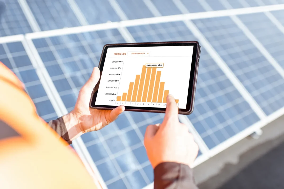
Modern solar power charge controllers and integrated systems typically provide operational visibility including:
These data points are used not only for real-time operation but also for long-term performance diagnostics and predictive maintenance.
| Alarm or trend | Likely cause | Recommended first action |
|---|---|---|
| Low PV voltage | String mismatch, shading, or wiring fault | Check string configuration and irradiance conditions |
| Low charge current | PV undersizing or thermal derating | Verify array size and controller temperature |
| Thermal derating event | Poor ventilation or high ambient temperature | Inspect installation environment and airflow |
| Communication loss | BMS/inverter protocol mismatch | Check wiring, protocol settings, and firmware |
| Frequent low-voltage disconnect | Battery undersized or excessive load | Review load profile and battery capacity |
Modern controllers may report PV voltage, PV current, PV power, battery voltage, charge current, battery temperature, state of charge where available, daily energy yield, fault alarms, and historical logs. Higher-end systems may integrate with SCADA, EMS, or building management platforms through RS485, Modbus, CAN, Ethernet, or other interfaces.
For multi-site operators, controller-level data supports remote diagnostics. If a telecom site reports low battery voltage, the O&M team can check whether the issue is low irradiance, PV input failure, controller fault, battery degradation, or load increase before dispatching a technician. This reduces unnecessary truck rolls and helps prioritize service response.
There is no universal service-life guarantee that applies across all projects. Field life depends on component quality, thermal stress, load profile, surge exposure, enclosure conditions, humidity, dust, maintenance practices, and installation quality. A controller installed in a ventilated indoor technical room may experience very different stress than one installed in a hot outdoor telecom cabinet.
For commercial planning, it is better to define inspection intervals, maintain spare units for critical sites, monitor thermal alarms, and review controller performance trends. Replacement planning should be part of the broader PV and battery O&M strategy rather than treated as an isolated component issue.
Preventive maintenance should include checking terminal tightness, dust buildup, corrosion, fan operation where applicable, temperature sensor condition, error logs, battery settings, firmware versions, communication links, surge protection status, and signs of overheating. Inspection frequency should reflect site criticality and environmental severity.
For remote infrastructure, maintenance windows may be limited and costly. In those cases, monitoring quality, spare parts availability, and modular design become economically important. A low-cost controller that requires frequent manual troubleshooting can quickly become expensive when site access is difficult.
Common failure modes include controller overheating, MOSFET or relay failure, communication loss, sensor fault, firmware misconfiguration, surge damage, incorrect charge profile, and battery over-discharge. Some faults create immediate downtime. Others quietly reduce battery life over months.
For critical loads, EPCs should consider redundancy, parallel controller architecture, spare controller inventory, alarm integration, and response-time commitments. The controller should be included in the project’s risk register, especially where batteries support telecom uptime, security systems, refrigeration, pumping, medical facilities, or remote monitoring equipment.
A controller datasheet provides the starting point, but professional procurement should evaluate technical fit, documentation quality, support capability, and lifecycle risk.
When evaluating manufacturers and suppliers, EPCs and distributors should assess factory-level engineering maturity, not only datasheet specifications.
Key due diligence criteria include:
These factors directly influence system downtime risk and lifecycle service cost.
Important specifications include maximum PV input voltage, MPPT operating voltage range, rated charge current, supported battery voltages, compatible chemistries, conversion efficiency, protection features, communication interfaces, operating temperature range, enclosure rating, derating behavior, certifications, warranty terms, and installation requirements.
The most important ratings are not always the largest numbers. A controller with a high peak current rating but limited thermal performance may be less suitable than a lower-rated industrial model with better derating and monitoring. Similarly, a wide PV input range is valuable only if it aligns with the selected module stringing strategy and site temperature conditions.
Warranty length alone is insufficient. EPCs and resellers should assess the RMA process, technical support responsiveness, firmware support, repair options, regional stock, documentation quality, and compatibility roadmap. If a controller fails at a remote commercial site, the key question is not only whether the warranty covers replacement. It is how quickly the site can be restored.
For distributors, regional spare parts and clear support escalation are important commercial differentiators. For EPCs, the ability to obtain consistent firmware, configuration files, and replacement units across several project phases can reduce operational complexity.
Standardizing on a limited set of controller models can simplify inventory, installer training, design templates, commissioning procedures, and O&M. This is especially useful for portfolio rollouts across telecom towers, agricultural facilities, rural commercial sites, warehouses, water systems, and remote infrastructure.
However, standardization should not override technical suitability. A controller family should cover the required PV voltage range, battery voltages, environmental ratings, certifications, and communication protocols for the target market. Regional conformity requirements, packaging quality, lead times, minimum order quantities, and documentation language should also be reviewed.
For commercial PV decision-makers, bankability is not limited to price or brand visibility. It includes manufacturing quality control, test evidence, compliance documentation, references in similar applications, technical roadmap, after-sales capacity, and long-term product availability.
A supplier that provides clear manuals, realistic derating data, configuration guidance, and responsive engineering support may reduce lifecycle risk more effectively than a lower-cost supplier with limited documentation. For EPCs bidding on commercial projects, this can affect design approval, commissioning efficiency, and customer confidence.
Before standardizing a controller platform across projects, EPCs should require:
Bankability should be evaluated based on tangible evidence, including:
These factors are often more important than nominal technical specifications when evaluating long-term project risk.
The charge controller is often a small share of total project CAPEX, but it can have a disproportionate impact on lifecycle cost. It influences energy harvest, battery protection, maintenance frequency, downtime risk, and system expandability.
A lower-cost controller can appear attractive during procurement, especially in price-sensitive markets. However, if it reduces energy harvest, limits PV string design, lacks proper battery compatibility, or increases field service calls, the apparent savings may disappear quickly.
Commercial buyers should evaluate the controller as part of the full solar battery charging system. The relevant question is not “what is the cheapest controller that meets nominal voltage and current?” It is “which controller reduces total project risk while meeting energy, battery, compliance, and service requirements?”
MPPT efficiency, correct charge profiles, temperature compensation, and reliable protection functions all contribute to usable energy and battery longevity. If MPPT improves energy harvest enough to reduce PV oversizing or improve battery recharge reliability, it can influence project payback. If accurate charging extends battery service life, the economic impact may be greater than the controller’s purchase price.
For commercial sites, uptime is often part of ROI. A solar controller serving a telecom tower, irrigation system, or security installation creates value by keeping the load operational. Downtime can be more expensive than incremental hardware cost.
OPEX includes technician time, transportation, spare parts, lost production, customer disruption, and emergency response. Remote sites amplify these costs. A service visit to a rural pumping station, mining support facility, or telecom tower can cost far more than the controller itself.
Monitoring, modular replacement, clear fault codes, and standardized spare units help reduce OPEX. In multi-site portfolios, small improvements in commissioning and diagnostics can produce significant operational savings across dozens or hundreds of installations.
Charge controllers influence lifecycle energy cost indirectly through conversion efficiency, battery health, maintenance frequency, and availability. EPCs should model controller selection as part of the broader PV-plus-storage financial case rather than treating it as a standalone line item.
In commercial storage projects, the battery is often the economic center of the system. Any device that affects battery charging quality affects the asset’s long-term value. A controller that protects the battery, communicates reliably, and operates efficiently supports lower lifecycle risk and more predictable project economics.
Commercial facilities often evolve. Loads increase, batteries are expanded, monitoring requirements change, or additional PV capacity is added. Controller architecture should support realistic expansion scenarios where possible.
Future expansion can be supported through voltage and current headroom, modular controller layouts, spare enclosure space, expandable combiner boxes, additional DC disconnect capacity, and communication architecture that can accept more devices.
However, headroom should be intentional. Oversizing a controller may improve flexibility, but it may also increase cost and affect operating efficiency at low load. EPCs should discuss expansion expectations with the owner early in the design process and document what can be expanded without major redesign.
Multiple controllers can improve scalability and redundancy. They also distribute heat and allow partial maintenance without shutting down all PV charging. This architecture is common in larger off-grid systems and modular commercial deployments.
The design must ensure consistent charge settings, balanced battery connections, suitable communication coordination, and clear monitoring. If controllers operate independently without aligned setpoints, they may interact poorly or charge unevenly. Commissioning records become especially important in multi-controller systems.
Commercial energy systems are becoming more connected. Controllers may need to interface with EMS platforms, smart meters, generator controllers, remote monitoring portals, and battery systems. Open communication protocols and accessible data are increasingly important for system integrators.
Before deploying a controller across multiple sites, integrators should verify protocol support, data availability, cybersecurity practices, firmware management, and remote access controls. Networked controllers should be treated as operational technology assets, not just electrical devices.
For portfolio deployments, standardization reduces design variation, procurement complexity, training time, and O&M workload. This is especially valuable for telecom networks, agricultural portfolios, warehouse fleets, rural commercial facilities, and distributed infrastructure.
A standardized controller platform allows installers to repeat known commissioning procedures, operators to interpret common alarms, and procurement teams to manage fewer spare parts. The best platform is not necessarily the one with the highest individual specification, but the one that consistently supports the portfolio’s electrical, environmental, compliance, and service requirements.
A solar power charge controller should be specified as part of the complete PV-plus-storage architecture, not as an isolated accessory. For professional projects, the right selection depends on MPPT performance, voltage and current headroom, battery chemistry, BMS communication, thermal derating, certifications, monitoring, installation quality, and lifecycle support. When these factors are addressed early, EPCs and system owners can reduce commissioning risk, protect storage assets, and improve long-term system availability.
A solar power charge controller regulates PV power to safely charge batteries and sits between the solar array and battery bank in DC systems. It prevents overcharging, deep discharge, and reverse current flow at night. It also helps maintain stable battery operating conditions under variable solar input. In some configurations, it can limit or disconnect output when battery voltage becomes unsafe. This directly improves battery safety and service life in commercial PV systems.
MPPT controllers are generally more efficient because they extract maximum power from the PV array and convert excess voltage into usable charging current. PWM controllers are simpler and only suitable when PV and battery voltages are closely matched. MPPT is preferred in most commercial and hybrid systems due to higher energy yield and flexibility. PWM may still be used in small or low-cost installations with stable conditions. The trade-off is higher performance versus lower system cost and complexity.
Standard grid-tied PV systems without batteries do not require a standalone charge controller because the inverter manages PV conversion. Charge controllers are required when batteries are part of the system and charging is done on the DC side. In many modern systems, this function is integrated into hybrid inverters or energy storage systems. The controller function still exists but may not be a separate device. System architecture determines whether it is physically required or embedded.
Sizing starts by matching the controller to battery voltage and system architecture requirements. PV string voltage must be checked under cold conditions to avoid exceeding controller input limits. PV current must also remain within the controller’s rated input capacity. Battery charging current is then calculated based on PV power and battery voltage. Final selection must follow manufacturer derating limits and system safety margins.
Yes, but compatibility depends on the specific lithium battery system and controller design. Some lithium batteries require strict voltage control and defined charging profiles. Advanced systems may also require BMS communication for safe operation. Not all lithium batteries or controllers support the same protocols or settings. Compatibility must always be verified against manufacturer specifications before deployment.
https://webstore.iec.ch/searchform&q=IEC%2062509








 Turkish
  Romanian