


Emergency solar backup for business is no longer a niche requirement for remote sites or sustainability-led companies. For commercial and industrial facilities, grid outages can stop production, interrupt cold storage, shut down communications, compromise security systems, and create direct revenue losses. For EPCs, PV installers, resellers, system integrators, and facility owners, the real question is not whether solar can support backup power, but how the system should be engineered, approved, commissioned, financed, and maintained so it performs when the grid fails.
A standard grid-tied solar PV system is not automatically a backup power system. In most jurisdictions, grid-connected inverters must disconnect during a utility outage to prevent unsafe islanding. A commercial PV backup power system therefore needs battery storage, backup-capable inverter architecture, transfer equipment, load management, protection devices, and a control strategy that allows selected loads to operate safely in island mode. For larger facilities, the solution may also need to coordinate with existing generators, UPS systems, building management systems, and utility interconnection requirements.
For B2B solar professionals, emergency backup is best treated as a business continuity project rather than a simple equipment sale. The design must start with the client’s operational risks, critical loads, acceptable downtime, outage duration assumptions, and lifecycle economics. A system that is correctly sized on paper but poorly commissioned, badly documented, or not maintained can fail at the exact moment it is needed. This guide explains the practical decisions behind commercial solar battery backup, solar-plus-storage for businesses, hybrid solar inverter systems, y sistema de almacenamiento de energía en baterías selection for commercial sites.
To deliver reliable outage resilience for commercial properties, it is essential to start with clear load planning and system design fundamentals.
Emergency backup systems are designed around essential loads, not total facility consumption. This distinction is central to both technical sizing and project economics. A 500 kW commercial building does not necessarily need 500 kW of backup power if only refrigeration, IT infrastructure, emergency lighting, security systems, communications equipment, and selected outlets must remain energized during an outage. Conversely, a smaller facility with motors, pumps, compressors, or medical equipment may require high surge capacity even if its average energy consumption is modest.
For EPCs and installers, the first project task is a critical load audit. This includes identifying which circuits must be backed up, when they operate, how much power they draw, and whether they have starting currents that exceed normal running load. Utility bills show monthly consumption and demand charges, but they rarely provide enough detail for backup design. Interval meter data, temporary load logging, equipment nameplate review, and facility operating schedules are more useful for determining real backup requirements.
A cold storage warehouse, for example, may prioritize refrigeration compressors, controls, defrost cycles, security, and limited lighting. A clinic may prioritize medical equipment, refrigeration for temperature-sensitive materials, communications, access control, and HVAC for selected rooms. A telecom site may require continuous DC power, battery autonomy, and remote monitoring more than conventional building loads. These differences explain why emergency solar backup for business must be engineered by application rather than sold as a standard package.
Below is a sample critical-load audit table to guide EPCs and facility owners in identifying and documenting backup requirements:
| Load Name | kW | Surge kVA | Runtime Priority | Backup Panel Assignment | Shedding Priority |
|---|---|---|---|---|---|
| IT Servers | 15 | 30 | High (24/7) | Critical Load Panel 1 | Low (Do not shed) |
| Refrigeration Compressors | 25 | 50 | High (24/7) | Critical Load Panel 1 | Low (Do not shed) |
| Emergency Lighting | 2 | 2 | High (24/7) | Critical Load Panel 2 | Low (Do not shed) |
| Security Cameras | 3 | 3 | Medium (During Outage) | Critical Load Panel 2 | Medium (Shed only if energy is limited) |
| Office HVAC | 18 | 22 | Medium (Business Hours Only) | Critical Load Panel 2 | High (Shed first if energy is limited) |
| Printers/Copiers | 1 | 1 | Low (Non-Essential) | Not Assigned | High (Never backup) |
Follow this streamlined project workflow for reliable deployment: define critical loads and outage objectives; select architecture; model kW, kWh, surge, and recharge requirements; confirm interconnection, code, fire, and utility constraints; procure certified compatible equipment; install and commission islanding operation; monitor, test, and maintain backup readiness.
Solar can power a business during a grid outage only if the system is specifically designed for backup or island operation. Most commercial solar backup systems power selected critical loads rather than the entire facility unless engineered and financed for whole-site islanding—this approach balances cost, reliability, and operational needs. Three distinct backup configurations should be distinguished: critical-load backup (powers only essential loads, e.g., IT, refrigeration, emergency lighting), whole-building backup (powers the entire facility, requiring larger inverter/battery capacity and utility approval), and full microgrid operation (integrates PV, batteries, generators, and controllable loads for complete grid independence, with advanced control systems to manage islanding and load dispatch).
A conventional grid-tied PV system normally shuts down when the grid fails because anti-islanding protection prevents the inverter from energizing utility lines that workers may assume are de-energized. This safety principle is embedded in interconnection rules and inverter standards in many markets, including requirements based on standards such as IEEE 1547 and IEC anti-islanding test methods. Anti-islanding protection is critical to protect utility workers who may be repairing power lines during outages, as unintended energization of de-energized lines could cause serious injury or death.
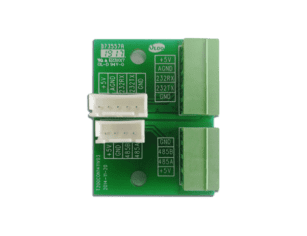
To operate during an outage, the system needs equipment that can disconnect from the utility and form or support a stable electrical island. This usually means a battery energy storage system, hybrid inverter or bidirectional battery inverter, automatic transfer equipment, a critical load panel, and a controller capable of managing voltage, frequency, load, and PV generation. Grid-forming capability is especially important because PV inverters alone typically follow an existing grid signal; they do not always create one. In a backup architecture, the battery inverter or microgrid controller often establishes the electrical reference that allows PV to continue operating safely.
It is important to note that some inverter architectures offer limited PV-only backup capability, which allows PV to power loads during outages without battery storage; however, this is rarely applicable for commercial facilities due to its unreliability (dependent on sunlight, no energy storage for nighttime or cloudy conditions) and inability to support surge loads or maintain stable island operation.
Transfer time also matters. UPS systems typically provide milliseconds-to-minutes of no-break continuity for sensitive electronics, while BESS and microgrid systems provide minutes-to-hours of backup power and PV recharge capability—this is why many commercial projects combine these technologies to ensure seamless continuity for all critical loads. Others, such as servers, controls, laboratory equipment, and data infrastructure, may require UPS support to bridge the gap. This is why many commercial projects combine solar-plus-storage with UPS systems rather than trying to replace every continuity asset with one technology.
A business continuity power solution is broader than backup energy capacity. It starts with the operational question: what must continue, for how long, and at what performance level? A retail store may need to keep payment systems, lighting, refrigeration, and security online for several hours. A manufacturing site may only need enough backup to safely stop production and avoid material loss. A healthcare or data facility may need layered redundancy, strict testing, and documented operating procedures.
Backup design should therefore reflect outage duration assumptions and risk categories. Revenue loss, safety exposure, spoiled inventory, customer service disruption, regulatory non-compliance, and equipment damage all influence system value. For some clients, the financial case is driven by demand charge management and energy savings during normal operation. For others, the main value is avoiding one high-impact outage every few years. EPCs should help clients quantify both measurable energy benefits and avoid operational losses.
Commercial solar backup solutions range from clean battery-supported PV systems to hybrid systems that also include generators. The correct choice depends on load size, outage duration, site constraints, fuel logistics, emissions objectives, and budget.
| Architecture | Best fit | Main advantage | Main limitation |
|---|---|---|---|
| Solar-plus-storage for businesses | Short to medium outages, critical loads, demand management | Fast response, low operating emissions, daily value potential | Battery autonomy is finite |
| Solar-plus-generator | Long-duration resilience, high-power loads, weak grids | Extended runtime with PV and battery fuel savings | More controls complexity and generator maintenance |
| UPS plus solar battery backup | IT, controls, healthcare, critical electronics | Very fast continuity for sensitive loads | UPS runtime is usually limited without larger storage |
| Off-grid or microgrid system | Remote sites or severe grid reliability issues | High independence and control | Higher design complexity, larger reserve margins |
Battery storage provides fast response and clean backup. Generators still have a role when outages are long, loads are very large, or the business requires redundant energy sources. In many commercial projects, the most resilient design is not “solar versus generator” but a coordinated hybrid architecture that uses PV and batteries first, then starts a generator only when needed.
The following table compares UPS, BESS, generator, and PV technologies to clarify their roles in commercial backup systems:
| Technology | Core Function | Key Capability | Limitation | Backup Panel Assignment | Shedding Priority |
|---|---|---|---|---|---|
| UPS | No-break power for sensitive electronics | Provides milliseconds-to-minutes of continuous power during transfer or short outages; protects against voltage sags/swells | Limited runtime without additional storage; not designed for long-duration outages | Critical Load Panel 1 | Low (Do not shed) |
| BESS | Longer-duration energy storage and island support | Delivers minutes-to-hours of backup power; enables islanded operation; supports PV recharge; provides grid services | Finite energy capacity; requires proper thermal management | Critical Load Panel 1 | Low (Do not shed) |
| Generator | Extended-duration backup power | Supports long outages (unlimited with fuel supply); handles high surge loads | Requires fuel storage/maintenance; emits emissions; slower startup than BESS | Critical Load Panel 2 | Low (Do not shed) |
| PV | Fuel-free generation and battery recharge | Generates clean energy to power loads and recharge BESS during daylight; reduces generator fuel use | Dependent on sunlight; cannot provide power at night/cloudy conditions; requires inverter support for islanding | Critical Load Panel 2 | Medium (Shed only if energy is limited) |
| Office HVAC | 18 | 22 | Medium (Business Hours Only) | Critical Load Panel 2 | High (Shed first if energy is limited) |
| Printers/Copiers | 1 | 1 | Low (Non-Essential) | Not Assigned | High (Never backup) |

When designing a commercial solar backup solution, accurate system sizing lays the foundation for reliable outage performance and cost efficiency. Properly calculating power needs, battery capacity, and inverter specifications ensures the setup matches site-specific operational demands without overengineering or underperformance.
Determining backup power requirements requires a structured, data-driven approach that moves beyond basic power and energy concepts to include load inventory, interval metering, surge measurement, runtime modeling, and reserve margin—all critical to ensuring the system meets operational needs during outages.
First, a comprehensive load inventory must be conducted to identify all potential critical loads, including their operating schedules, power draw (kW), and surge requirements (kVA) during startup. This inventory distinguishes between essential, deferrable, and nonessential loads, ensuring only critical loads are included in backup sizing to avoid unnecessary costs. Next, interval metering (typically 15-minute or hourly data) provides detailed insights into load profiles, revealing peak demand times, load variability, and usage patterns that monthly utility bills fail to capture. This data is essential for understanding coincident peak demand—the maximum power draw when multiple critical loads operate simultaneously.
Surge measurement is another key step: inductive loads (e.g., motors, compressors) require significantly more power during startup (surge kVA) than their normal running load (kW), and the backup system (especially inverters) must be sized to handle these surges to avoid tripping or equipment damage. Runtime modeling involves calculating the required energy (kWh) based on the critical load’s kW and the expected outage duration, while also accounting for PV recharge potential during daylight hours. Finally, a reserve margin (typically 10–15%) must be added to the calculated capacity to account for unexpected load increases, battery degradation, and temperature-related performance losses.
A practical sizing process builds on these steps by first finalizing the load inventory, then using interval metering data to refine peak demand and load variability, measuring surge requirements for inductive loads, modeling runtime with and without PV recharge, and applying a reserve margin to ensure reliability.
| Facility type | Typical critical loads | Key sizing issue |
|---|---|---|
| Office building | IT, lighting, access control, communications, limited HVAC | Transfer time and tenant continuity |
| Cold storage | Refrigeration, controls, doors, monitoring, lighting | Compressor surge and thermal holdover |
| Clinic or laboratory | Medical equipment, refrigeration, communications, selected HVAC | Compliance, UPS coordination, testing |
| Telecom site | DC power systems, cooling, monitoring, security | Continuous uptime and remote diagnostics |
| Manufacturing plant | PLCs, pumps, compressed air, selected process equipment | Motor loads and safe shutdown sequencing |
EPCs should avoid sizing up from monthly utility bills alone. A bill may show peak demand, but it does not identify which circuits created the peak or whether those circuits need backup. Load studies, interval metering, and facility interviews reduce the risk of oversizing expensive batteries or under-sizing critical inverter capacity, ensuring the system is both cost-effective and reliable.
Battery capacity is often misunderstood because nameplate capacity is not the same as usable capacity. A battery rated at 500 kWh may not deliver the full amount in normal operation once depth of discharge limits, reserve margins, temperature effects, degradation, and control settings are considered. For commercial backup applications, usable kWh and lifecycle performance matter more than nameplate values.
The core relationship is simple, but the assumptions behind it are important.
| Sizing factor | Practical meaning |
|---|---|
| Critical load kW | Maximum backed-up load that may operate at one time |
| Required runtime | Number of hours the load must be supported |
| Usable battery capacity | Energy available after DoD, reserve, and derating |
| C-rate | Ability of the battery to deliver required power |
| Degradation allowance | Capacity margin for end-of-warranty performance |
Lithium-ion battery energy storage systems are common in commercial PV applications because they offer high efficiency, modularity, relatively low maintenance, and strong power response compared with many legacy chemistries. However, chemistry selection still matters. Lithium iron phosphate is widely used where thermal stability and long cycle life are priorities. Other lithium chemistries may offer different density or power characteristics. The best choice depends on enclosure design, certification, application duty cycle, thermal management, warranty terms, and local safety requirements.
When determining battery autonomy, it is critical to model runtime both with and without PV recharge, as solar availability can significantly extend backup duration during daylight hours while also introducing variability in recharge rates. Three key autonomy scenarios should be evaluated to ensure comprehensive resilience: battery-only runtime (for nighttime or low-sun outages), battery plus daytime PV support (for extended outages with adequate solar irradiance), and multi-day outage with reduced solar production (e.g., winter, cloudy weather, or shading).
Below is an illustrative sizing workflow—intended to demonstrate the process rather than serve as a final engineering rule—to guide commercial backup battery sizing: For a facility with an 80 kW critical load and a required 6-hour runtime, the total energy required is 480 kWh (80 kW × 6 hours). With a 90% depth of discharge (DoD) limit, the minimum usable battery capacity needed is approximately 533 kWh (480 kWh ÷ 0.9). Accounting for battery degradation over time and a reserve margin for unexpected load increases, the installed battery capacity should typically range from 600–650 kWh. Additionally, separate checks must be performed to ensure the inverter’s power rating can support the 80 kW critical load (plus any surge capacity for motor starting or peak demand) to avoid underperformance during outages.
Inverter selection is one of the most important design decisions in an emergency solar backup for business project, making reliable fabricación de inversores solares a core consideration for system performance and long-term compliance. Standard grid-tied inverters are designed to export PV power when the utility grid is present. Backup systems require additional capability: the ability to operate with batteries, manage islanding, maintain stable voltage and frequency, and coordinate with transfer equipment and loads.
Hybrid inverters combine PV and battery functions in one platform for certain system sizes and configurations. Bidirectional battery inverters charge and discharge battery energy storage systems and can support AC-coupled PV architectures. Grid-forming inverters can establish a stable electrical reference during islanded operation. Microgrid controllers supervise multiple assets, including PV inverters, batteries, generators, breakers, and load controllers.
Modern smart inverters also deliver advanced grid-service capabilities that underpin reliable backup and grid resilience, with distinct operational modes and adjustable response parameters tailored for commercial islanding and grid-connected scenarios.
Grid-following inverters rely on an existing stable grid voltage and frequency reference to synchronize and export power, shutting down automatically during outages to comply with anti-islanding rules.
Commercial backup inverters must support voltage ride-through and frequency ride-through functions, allowing the system to remain online and avoid unnecessary tripping during temporary grid fluctuations, sags, swells, and minor frequency deviations common on weak distribution networks.
Integrated Volt-VAR and Volt-Watt control functions enable inverters to dynamically adjust reactive power and real power output based on measured grid voltage, stabilizing local power quality and reducing stress on backup loads during peak operation.
Robust reactive power support is essential for commercial emergency systems, balancing power factor, mitigating voltage drop across long feeder runs, and supporting inductive motor loads during islanded backup operation.
Ramp-rate control limits how quickly PV inverter output rises or falls, preventing abrupt power swings that could destabilize battery storage, critical loads, or local microgrid voltage and frequency.
Export limiting and zero-export operation modes allow commercial solar backup systems to comply with utility interconnection rules, restricting power flow back to the grid while prioritizing on-site critical load self-consumption during normal and outage conditions.
Frequency-watt response automatically reduces PV power output when grid frequency drifts outside predefined thresholds, supporting grid stability and preventing overload conditions in islanded backup microgrids.
| System Configuration | Use Case | Core Benefit | Key Consideration |
|---|---|---|---|
| DC-coupled solar-plus-storage | New builds and PV-to-battery charging efficiency | Higher round-trip charging efficiency, simplified single-point controls | Less flexible for retrofitting existing standalone PV arrays |
| AC-coupled storage | Retrofit for existing PV systems | Works with legacy inverters, no full PV rework needed | Slightly lower overall charging efficiency compared to DC coupling |
| Hybrid inverter architecture | Smaller or modular commercial systems | All-in-one PV, battery, and grid interconnection | Limited scalability for large industrial load portfolios |
Designers should evaluate black-start capability, surge rating, transfer time, three-phase compatibility, neutral bonding strategy, short-circuit contribution, harmonic performance, communications protocols, and manufacturer-approved battery pairings. These issues are not secondary details; they determine whether the backup system operates reliably under real outage conditions.
PV array sizing for backup requires more than annual energy modeling. The array must support normal energy generation while also helping recharge the battery after or during an outage. Seasonal production, local irradiance, weather variability, roof or land constraints, module orientation, shading, and DC/AC ratio all influence resilience performance.
For example, a facility may have enough annual solar production to offset a large share of consumption, but still have insufficient winter production to recharge batteries during a multi-day outage. A warehouse with a large flat roof may have strong PV potential, while a dense urban facility may have limited roof area and shading challenges. Ground-mounted systems may solve space constraints but introduce civil work, fencing, security, and permitting considerations.
Professional designers should model expected outage windows, low-sun scenarios, battery state-of-charge strategy, and critical load scheduling. For resilience-focused projects, it may be appropriate to maintain a minimum battery reserve rather than optimizing every day for energy arbitrage or peak shaving.

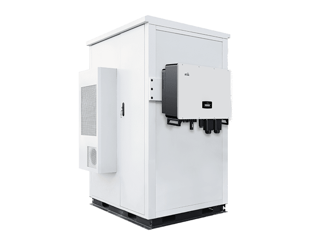
Every commercial solar backup system relies on several core hardware and electrical components working in tandem to deliver reliable islanding performance and critical load protection. From battery storage and inverters to distribution hardware and monitoring tools, each element must be carefully selected and integrated to meet operational safety, code compliance, and long-term resilience goals.
A battery energy storage system for commercial sites should be evaluated as an integrated product, not only as cells or cabinets. Key selection factors include usable capacity, power rating, cycle life, C-rate, enclosure rating, thermal management, fire safety features, battery management system functionality, monitoring access, and modular expansion options. Manufacturer bankability, warranty language, spare parts availability, and after-sales technical support are equally important for EPCs and resellers.
The application should drive procurement. A battery used mostly for emergency backup may experience few cycles but must maintain readiness. A battery used daily for demand charge reduction or time-of-use optimization will cycle more frequently and may age faster. A system designed for both backup and daily dispatch needs controls that preserve emergency reserve while still generating economic value during normal grid operation.
Transfer equipment and electrical distribution design determine which loads are actually protected. Automatic transfer switches, critical load panels, smart load controllers, breakers, disconnects, and labeling all contribute to safe operation. Not every circuit should be backed up. Nonessential HVAC, large process loads, EV chargers, or production equipment may exceed inverter capacity or drain batteries too quickly.
For commercial retrofits, panel modifications often require careful coordination with facility electrical staff. Shutdown windows may be limited, and some loads may not be well documented. Installers should verify panel schedules, conductor sizes, grounding, protection coordination, and available physical space before finalizing design. A technically strong battery and inverter package can still underperform if the backed-up load panel is poorly selected.
Monitoring is not optional for commercial solar battery backup. Operators need visibility into battery state of charge, inverter status, PV production, alarms, temperature, fault logs, and backup readiness. For EPCs and O&M providers, remote diagnostics reduce truck rolls and shorten response times. For multi-site portfolios, centralized dashboards help identify underperforming assets, communication failures, and recurring inverter or battery alarms.
An energy management system can also decide how the battery is dispatched during normal operation. It may prioritize peak shaving, time-of-use optimization, backup reserve, PV self-consumption, generator support, or demand response participation. The more complex the use case, the more important it becomes to define control logic clearly during project development.
Balance-of-system quality has a direct impact on reliability. Combiner boxes, disconnects, fuses, breakers, surge protection devices, grounding systems, meters, enclosures, cabling, connectors, and communications hardware must be properly specified and installed. Many field failures come from terminations, moisture ingress, incorrect protection settings, inadequate labeling, or communication wiring errors rather than from the major equipment itself.
For emergency backup projects, BOS failures can be especially costly because the system may appear healthy during normal operation but fail during transfer, islanding, or high-load discharge. EPC quality control should therefore include inspection of mechanical installation, torque records, cable routing, labeling, protection settings, and communications testing.
Navigating grid rules, safety certifications and on-site compliance is non-negotiable for commercial solar backup deployments.
Commercial backup systems must comply with grid interconnection and anti-islanding requirements. Utilities may require application forms, single-line diagrams, equipment certifications, export limits, relay settings, protection studies, witness testing, and commissioning documentation. In some cases, interconnection review can become a project schedule driver, especially when the system is large, exports power, or interacts with medium-voltage infrastructure.
| System Type | Key Interconnection Requirements & Risks |
|---|---|
| Non-export backup system | The utility may still require proof of export control and anti-islanding protection to prevent unintended backfeed to the grid during outages. |
| Exporting PV-plus-storage system | Export limits, specialized metering, inverter configuration settings, and possibly grid impact studies may be required to ensure compatibility with utility distribution systems. |
| Medium-voltage C&I system | Protection coordination, precise relay settings, and utility witness testing are typically required to validate safe interconnection with medium-voltage infrastructure. |
| Generator-integrated microgrid | Clear operating modes must be defined and documented to avoid unsafe backfeed, frequency instability, and non-compliant islanding during grid outages. |
Expected utility-interconnection document types include relay settings, anti-islanding test procedure, export-control method, protection coordination study, and one-line diagrams showing both normal grid-connected operation and islanded backup operation—all of which are critical for utility review and approval.
Global projects must be reviewed against local grid codes and utility rules. Standards such as IEEE 1547 provide a widely recognized framework for distributed energy resource interconnection in the United States, while IEC standards are commonly referenced in international PV and inverter testing contexts. However, the authority having jurisdiction, utility, and national code requirements ultimately determine what is acceptable for a specific site.
Commercial solar-plus-storage systems involve PV DC circuits, AC distribution, battery cabinets, power conversion equipment, controls, communications, and often fire safety systems. Certified equipment and documented compliance reduce project risk. Depending on the region, applicable requirements may address PV installation practices, energy storage safety, inverter interconnection, fire protection, emergency shutdown, ventilation, and working clearances.
EPCs should avoid treating certification as a procurement afterthought. If a battery or inverter lacks documentation required by the local authority, the project may face permitting delays or redesign. Product datasheets, installation manuals, compliance certificates, test reports, and warranty documents should be reviewed before purchase orders are finalized.
A complete certification checklist must cover key North American and national electrical standards to validate system safety, interconnection, and fire compliance for commercial solar-plus-storage deployments. Key applicable certifications and codes include UL 9540 for full energy storage system certification, UL 9540A for thermal runaway fire propagation testing of battery enclosures, UL 1741 / UL 1741 SA / SB for inverter and smart inverter interconnection compliance across North America, alongside NEC Article 690 governing PV system installation, NEC Article 705 for interconnected distributed power production sources, and NEC Article 706 dedicated to stationary energy storage system safety and installation requirements.
EPCs must coordinate with the local fire marshal and authority having jurisdiction (AHJ) to secure review and approval of all solar-plus-storage safety components, ensuring alignment with local fire and electrical codes. All systems must include comprehensive fire suppression or detection documentation, outlining the type, placement, and operational parameters of fire safety equipment to demonstrate compliance with AHJ requirements. Emergency responder access and clear signage are also mandatory: emergency responders must have unobstructed access to battery enclosures, PV arrays, and control equipment, with standardized signage identifying hazards, emergency shutdown points, and equipment locations. Additionally, EPCs should verify UL 9540 listing for all energy storage systems, review thermal runaway test data (per UL 9540A), and confirm AHJ requirements for NFPA 855 compliance—including spacing, ventilation, signage, and emergency response documentation—to avoid permitting delays or non-compliance issues.
Battery placement affects safety, maintenance access, insurance review, and approval by fire or building authorities. Commercial battery energy storage systems may require spacing, ventilation, thermal runaway mitigation, fire detection, signage, barriers, emergency access, and dedicated clearances. Indoor installations raise different concerns from outdoor containerized or cabinet-based systems. Key commercial BESS fire-safety decision points include selecting appropriate fire suppression/detection systems, determining ventilation requirements, establishing separation distances, and configuring emergency access—all of which must align with local codes and NFPA 855 standards.
Indoor vs. outdoor battery siting involves key tradeoffs: indoor installations offer better protection from weather, vandalism, and temperature extremes but require enhanced ventilation, fire suppression, and gas detection to mitigate risks; outdoor installations simplify ventilation and fire venting but may face exposure to harsh weather, require more space for separation distances, and need weatherproof enclosures to protect battery components.
Separation distances are critical: batteries must be placed at specified distances from occupied areas, exits, and combustible materials (e.g., walls, furniture, or fuel storage) to reduce fire spread risk, with exact distances dictated by AHJ requirements and NFPA 855. HVAC or liquid cooling systems are mandatory for maintaining safe battery operating temperatures (typically 20–25°C); HVAC systems must be sized to handle heat output from batteries during charging/discharging, while liquid cooling is preferred for larger BESS installations or high-temperature environments to ensure consistent thermal management.
For large or indoor BESS installations, deflagration venting or gas detection is applicable: deflagration vents redirect pressure and flames from thermal runaway to safe exterior areas, while gas detection systems monitor for hydrogen or other toxic gases emitted during battery failure, triggering alarms or emergency shutdowns. Fire department access routes must be maintained at all times—routes should be unobstructed, wide enough for emergency vehicles, and clearly marked, with direct access to battery enclosures and emergency shutdown points. Emergency shutdown labeling is required on all battery cabinets and control panels, with clear, standardized signage indicating the location of shutdown switches, emergency contacts, and hazard warnings.
Battery cabinet spacing and aisle clearances must comply with manufacturer guidelines and AHJ requirements: cabinets should be spaced to allow for maintenance access, heat dissipation, and emergency egress, with aisle clearances typically ranging from 3–5 feet depending on cabinet size and installation type. Before finalizing BESS design, EPCs must coordinate with insurance carriers for review—insurers may require specific fire safety features, separation distances, or thermal runaway mitigation measures to approve coverage. Finally, thermal runaway test documentation (per UL 9540A) must be provided to demonstrate that battery enclosures and fire safety systems can contain or mitigate thermal runaway events, a requirement for AHJ and insurance approval.
High-temperature environments can also accelerate battery degradation and reduce usable capacity. Early coordination with facility managers, safety officers, insurers, and permitting authorities reduces the risk of late-stage redesign. Designers should consider how emergency responders will identify and isolate equipment, how maintenance teams will access cabinets, and how thermal management systems will perform under local climate conditions.
Early coordination with facility managers, safety officers, insurers, and permitting authorities reduces the risk of late-stage redesign. Designers should consider how emergency responders will identify and isolate equipment, how maintenance teams will access cabinets, and how thermal management systems will perform under local climate conditions.
A strong documentation package improves approval speed and long-term serviceability. For commercial PV backup power systems, typical documentation includes electrical single-line diagrams, site layouts, equipment datasheets, battery specifications, protection settings, structural details, cable schedules, monitoring architecture, emergency shutdown procedures, commissioning plans, and O&M manuals.
| Document | Por qué es importante |
|---|---|
| Diagrama unifilar | Shows electrical architecture, protection, and interconnection |
| Battery and inverter datasheets | Confirms ratings, certifications, and operating limits |
| Protection settings | Supports utility review and safe operation |
| Commissioning plan | Defines tests before handover |
| O&M manual | Supports maintenance, troubleshooting, and training |
For resellers and EPCs working across multiple similar sites, standardized documentation templates can reduce engineering time and improve repeatability.
Successful emergency solar backup performance relies heavily on careful on-site evaluation, professional installation, thorough commissioning, and proper coordination with existing facility equipment.
A commercial site assessment should evaluate electrical room capacity, switchgear condition, transformer capacity, roof or land availability, structural loading, cable routes, fire access, communications connectivity, and existing generators or UPS systems. It should also account for operational constraints such as restricted work hours, security procedures, production schedules, and planned shutdown windows.
Many project risks emerge from assumptions made before installation. A switchboard may lack spare capacity. A roof may need structural reinforcement. Cable routes may be longer or more complex than expected. Existing generator controls may not support the intended operating sequence. Detailed surveys reduce change orders and help EPCs produce realistic schedules and budgets.
Commissioning is where the design is proven. A commercial backup system should be tested under realistic operating conditions before handover. This includes inverter operation, battery charge and discharge verification, transfer switch operation, islanding tests, load transfer validation, monitoring setup, emergency shutdown checks, alarms, and communication links. Where safe and permitted, the facility should simulate a grid outage and confirm that critical loads operate as expected.
Documented results are essential. The client should receive evidence of tested backup capacity, transfer behavior, control settings, battery reserve strategy, and alarm response procedures. Facility staff also need training on what the system will and will not support during an outage. Without this step, clients may assume the system backs up more loads or runs longer than it actually can.
Many businesses already have backup assets. Solar-plus-storage may need to coordinate with diesel generators, gas generators, UPS systems, automatic transfer switches, building automation systems, and process controls. Poor integration can cause unsafe backfeed, nuisance trips, frequency instability, or inefficient generator loading.
Technical generator coordination requires careful attention to five key areas: generator minimum loading (to prevent wet stacking, generators must operate above a minimum load threshold, typically 30–50% of rated capacity, with PV/BESS used to supplement load when needed), start/stop sequencing (generators should start only when battery state of charge (SOC) falls below a predefined threshold, and stop when SOC is restored to a safe level), frequency stability (the microgrid controller must synchronize generator output with BESS/PV to maintain consistent frequency, avoiding fluctuations that could damage sensitive loads), generator charging of batteries (generators can be configured to charge BESS during extended outages when PV is unavailable, with charging rates controlled to avoid battery damage), and load-shed logic (noncritical loads should be shed before generators start or if generator capacity is exceeded, ensuring critical loads remain powered).
A sample control sequence illustrates how these components work together: When the grid fails, the UPS immediately bridges power to sensitive electronics (e.g., servers, medical equipment) to avoid downtime. Simultaneously, the battery inverter forms a stable island, and PV begins powering critical loads where sunlight is available. If the battery SOC falls below a predefined threshold (e.g., 20%), the generator starts and ramps up to minimum loading; the generator then supplements PV/BESS to power critical loads and recharge the battery. If the generator is unavailable (e.g., fuel shortage, mechanical failure), noncritical loads (e.g., office HVAC, non-essential lighting) are shed to extend battery runtime for critical loads.
Operating modes should be defined clearly. The system may run PV-first during daylight, battery-first for short outages, generator-assisted for long outages, or emergency-only with battery reserve held at a minimum level. For critical facilities, the control sequence should be tested and documented so operators know when generators start, when batteries discharge, and how loads are shed if energy is limited.
The most common reliability problems are often practical rather than theoretical. Incorrect critical load panel selection, undersized conductors, weak communication wiring, poor enclosure placement, insufficient surge protection, inadequate labeling, incorrect firmware versions, and incomplete commissioning can all undermine performance. Backup systems are more complex than standard grid-tied PV because they must operate correctly in both grid-connected and islanded modes.
A disciplined quality process should verify equipment compatibility, wiring, protection settings, torque values, thermal clearances, communications, monitoring, and user training. For EPCs, these checks protect margins as much as they protect clients; emergency service calls after a failed outage event are expensive and reputationally damaging.
Proper ongoing care and lifecycle planning directly determine how reliably commercial solar backup systems perform over years of operation, starting with battery health, warranty terms, and serviceable lifespan.
Commercial battery systems degrade over time. Degradation is influenced by cycle count, depth of discharge, temperature, charge and discharge rates, state-of-charge management, and operating mode. Backup-reserve batteries can degrade and age significantly even without frequent cycling, particularly when persistently held at a high state of charge or exposed to elevated ambient temperatures for prolonged periods. A battery used only for backup may age mainly by calendar time and environmental conditions. A battery used daily for peak shaving may reach throughput limits sooner.
Warranty terms may include years of operation, energy throughput, capacity retention, usage restrictions, temperature limits, and maintenance obligations. EPCs and resellers should explain these terms clearly. A client expecting both daily savings and full emergency autonomy must understand how dispatch strategy affects usable life and warranty compliance.
Clear end-of-life capacity thresholds define when commercial BESS assets require intervention, with most industry and warranty standards marking end-of-life at 60 to 80 percent of original usable capacity, at which point runtime performance and surge capability can no longer meet design backup requirements. Asset planning must evaluate battery augmentation versus full replacement strategies: targeted module or cabinet augmentation can restore usable capacity at lower cost and shorter downtime for partially degraded fleets, while full system replacement becomes necessary when widespread cell degradation, obsolete hardware, or expired warranty coverage make incremental upgrades uneconomical.
Project planning must also verify local manufacturer recycling or take-back program availability, as commercial lithium-ion BESS cannot be disposed of through standard waste channels and require formal asset recovery pathways. Hazardous material transport regulations govern all removal and relocation of degraded or end-of-life battery cabinets, mandating certified packaging, licensed carriers, and compliant routing to approved recycling or disposal facilities. Decommissioning cost assumptions must be explicitly embedded in full lifecycle ROI and financial modeling, including labor, permitting, transport, recycling fees, and temporary backup provisions during system removal. Manufacturers hold defined responsibility for providing end-of-life guidance, performance degradation documentation, compliance certificates, and warranty closure paperwork, all of which must be retained for site compliance, insurance records, and future facility audits.
Emergency backup systems should be maintained and periodically tested, not simply installed and ignored. Preventive maintenance may include visual inspections, firmware updates, thermal checks, electrical testing, torque verification, cleaning where required, alarm review, battery health assessment, enclosure inspection, and communication testing. The schedule should match the criticality of the loads. A retail backup system may not need the same maintenance intensity as a healthcare, telecom, or industrial control application.
O&M providers can add value by combining preventive inspections with performance analysis. If battery capacity is declining faster than expected, if inverter alarms repeat, or if communications are intermittent, these issues should be corrected before a grid outage exposes them.
Remote monitoring is most valuable when paired with a response workflow. Alerts should be assigned severity levels. Fault codes should trigger defined actions. Spare parts availability should be planned. Technician dispatch expectations should be agreed in the service contract. For multi-site commercial portfolios, centralized monitoring can identify patterns across assets and prioritize service based on business risk.
Monitoring platforms that support data export, fleet views, alarm history, and integration with building management systems can improve operational control. However, cybersecurity and access permissions should also be considered, especially for systems connected to facility networks or remote control platforms.
Robust cybersecurity implementation begins with role-based access control that restricts monitoring, configuration, and operational permissions to only assigned personnel based on job function, preventing unauthorized system changes or data access.
Strict remote firmware update permissions must be enforced to limit firmware uploads and system parameter adjustments to approved admin users only, blocking unvetted remote modifications that could compromise stability or safety.
All remote access should rely on dedicated VPN or secure gateway infrastructure to encrypt data transmission and create isolated access pathways outside public internet exposure.
Formal API access controls are required to limit third-party platform integrations, restricting data sharing and system command access to validated endpoints only.
Network segmentation practices must separate solar and BESS monitoring systems from core critical facility operational networks to contain potential cyber threats and prevent lateral movement across site infrastructure.
Comprehensive immutable logging of all remote commands, parameter changes, firmware updates, and user access events must be maintained for audit, compliance, and post-incident investigation purposes.
A formal incident response process for monitoring platform compromise must be established to minimize operational disruption and security risks, with clear steps and responsibilities:
If a backup system is not maintained, the facility may not discover problems until an outage occurs. Battery usable capacity may decline. Transfer equipment may fail to operate. Inverter faults may go unresolved. Communications may be lost. Protection devices may trip unexpectedly. Firmware or settings may become inconsistent after equipment changes.
The operational consequence is straightforward: critical loads may not receive power when needed. For B2B solar professionals, this is a key client education point. Emergency solar backup for business is an operational asset, not only a capital asset. Its readiness must be verified through monitoring, maintenance, and periodic testing.

Evaluating commercial solar backup requires a full financial breakdown across upfront investment, ongoing expenses, long-term returns, and total lifecycle performance to deliver accurate business justification.
ROI for solar backup should include more than energy savings. A standard PV-only project may be evaluated primarily on electricity offset, tariffs, incentives, and payback. A commercial solar battery backup project adds resilience value, avoided outage losses, demand charge reduction where applicable, time-of-use optimization, maintenance costs, battery augmentation or replacement assumptions, and financing structure.
Avoided outage cost is often the hardest but most important variable. A small office may experience inconvenience and lost productivity. A cold storage facility may lose inventory. A manufacturer may lose production batches, labor hours, and delivery commitments. A data or telecom facility may face service-level penalties. EPCs should help clients estimate outage cost by hour, probability of outage, and operational impact.
Capital cost depends on project scope, site conditions, and equipment architecture. Major cost drivers include PV modules, mounting systems, battery energy storage system, inverters, switchgear, transfer equipment, engineering, permitting, installation labor, structural upgrades, fire safety modifications, monitoring, and commissioning. Retrofit complexity can be a major factor, especially when electrical rooms are crowded or switchgear upgrades are required.
| Categoría de costes | Typical influence on budget |
|---|---|
| Battery capacity and power rating | Often the largest backup-specific cost driver |
| Inverter and controls | Determines islanding, dispatch, and compatibility |
| Switchgear and transfer equipment | Critical for safe load separation and operation |
| Engineering and permitting | Higher for complex interconnection or fire review |
| Mano de obra de instalación | Site access, shutdown windows, and retrofit complexity matter |
Transparent cost breakdowns help clients understand why backup-capable systems cost more than standard grid-tied PV. They also reduce disputes when scope changes arise from site conditions.
Operating costs may include preventive maintenance, monitoring subscriptions, software licenses, inspections, spare parts, thermal management energy use, battery augmentation, and eventual battery replacement. Service contracts should define inspection frequency, remote monitoring responsibilities, response times, exclusions, and warranty claim support.
Lifecycle planning is particularly important when batteries are used for both backup and daily economic dispatch. If a project’s financial model assumes 15 years of service but the duty cycle suggests earlier augmentation, the ROI calculation should reflect that. A realistic lifecycle model builds more trust than a simple payback estimate that ignores degradation.
Payback period, levelized cost of energy, and lifecycle cost analysis remain useful, but resilience projects are not judged by energy savings alone. A facility with high downtime costs may justify investment even when simple payback is longer than a PV-only system. Conversely, a site with low outage risk and limited critical loads may prefer a smaller system focused on energy savings and short-duration backup.
The strongest financial cases often combine multiple value streams: PV energy offset, demand charge management, time-of-use optimization, incentives where available, and business continuity. EPCs should model these separately so the client can see which assumptions drive value.
When selecting hardware for commercial solar backup projects, partnering with qualified suppliers and rigorous evaluation processes directly impact system reliability, compliance, and long-term operational value for industry professionals.
Supplier reliability matters because commercial backup systems must be supported for many years. EPCs and resellers should evaluate financial stability, product track record, commercial references, warranty process, documentation quality, technical support, training resources, and spare parts availability. A low-cost product can become expensive if commissioning support is weak or replacement components are difficult to source.
For channel partners, manufacturer support also affects reputation. When a backup system fails, the client usually calls the installer or EPC first, regardless of whether the root cause is a product issue. Supplier evaluation should therefore include after-sales capability, not only procurement price.
Component compatibility is central to backup reliability. Battery-inverter pairings should be approved by manufacturers or validated through application documentation. Communication protocols, firmware versions, monitoring integration, protection settings, and control logic must be aligned. Mixing components without clear support can create commissioning delays and ambiguous warranty responsibility.
System integrators should be especially careful when adding storage to existing PV systems. AC-coupled retrofits can work well, but the controller must manage PV output, battery charging, load behavior, and anti-islanding requirements. Existing inverter settings and utility approvals may need revision.
Commercial PV schedules are often sensitive to tenant operations, production shutdowns, fiscal-year budgets, and incentive deadlines. Batteries, switchgear, transformers, and inverters can have long lead times, and delays can disrupt commissioning. For international projects, customs, freight handling, warehousing, and local certification documentation may also affect delivery.
Resellers and EPCs should evaluate suppliers on delivery reliability, packaging quality, documentation completeness, and replacement part availability. Procurement planning should begin early enough to align equipment delivery with permitting, civil work, electrical installation, and commissioning windows.
Backup systems require more training than standard PV systems. Installers need to understand battery safety, inverter configuration, transfer equipment, communication networks, monitoring setup, commissioning tests, and emergency procedures. Technical training and commissioning support reduce field errors and improve customer confidence.
This is particularly important for installers expanding from residential or simple commercial PV into solar-plus-storage for businesses. The electrical scale, code requirements, documentation expectations, and operational consequences are more demanding in commercial environments.
EPC Procurement Submittal Checklist
The following checklist outlines all required documents, verifications, and commitments that EPCs must obtain and submit during the procurement process to ensure equipment compatibility, compliance, and long-term support:
As commercial solar backup deployments grow beyond single-site installations, forward-looking planning for scalability, portfolio rollouts, and future system expansion becomes essential for long-term value and operational flexibility.
Commercial clients may add EV charging, new HVAC loads, production equipment, data infrastructure, or additional floor space after the original installation. If the backup system is designed with no expansion path, future upgrades may require expensive retrofits. EPCs should consider modular battery cabinets, inverter capacity, switchgear headroom, spare communication capacity, and physical space for additional equipment.
Future expansion should not be assumed without engineering review. Adding batteries changes fault current, protection, controls, ventilation, fire safety considerations, and sometimes interconnection approvals. However, planning for expansion during the initial design can significantly reduce future cost and disruption.
Retail chains, warehouses, healthcare networks, schools, telecom operators, and distributed commercial portfolios benefit from standardization. Repeatable equipment packages, consistent monitoring platforms, common documentation, and standardized maintenance procedures make deployment easier across many locations. Fleet-level monitoring also allows operators to compare performance and prioritize service.
At the same time, each site still needs local assessment. Utility rules, tariffs, roof conditions, load profiles, climate, and permitting requirements can vary significantly. The best portfolio strategy combines standardized design templates with site-specific engineering review.
Emergency solar backup can evolve into a broader microgrid or distributed energy resource strategy. Once a facility has PV, batteries, controllable loads, and possibly generators, it can use the same platform for peak shaving, demand response, time-of-use optimization, generator runtime reduction, and resilience. The key is defining priorities. A system optimized only for daily energy savings may not preserve enough reserve for emergency backup unless the EMS is configured accordingly.
System integrators should ask whether the client wants emergency-only backup or a flexible energy platform. The answer affects inverter selection, metering, controls, battery warranty assumptions, and financial modeling.
This section defines clear decision boundaries to identify scenarios where standalone solar backup is functionally inappropriate and a hybrid layered architecture becomes mandatory, rather than merely outlining generator pairing options. Standalone solar backup fails to meet operational requirements when facing sustained ultra-high continuous load profiles, multi-day extended outage expectations, severely constrained rooftop or ground footprint, persistently low solar irradiance, rigid utility interconnection limitations, or regulatory mandates for fully redundant power infrastructure. These boundary conditions eliminate standalone solar-plus-storage as a viable primary solution and require integration with supplementary assets including generators, extended UPS frameworks, bulk fuel storage, or utility feed upgrades.
This framework does not diminish the core value of solar backup but establishes clear deployment limits. PV and batteries remain ideal for short-duration critical load resilience, emission-free operation, and ongoing demand management savings, yet they must be positioned as one component within a broader business continuity strategy whenever decision boundary thresholds are exceeded.
Emergency solar backup for business should be developed as a complete resilience project, not as an add-on battery sale. The strongest projects begin with critical load definition, realistic outage assumptions, and financial risk analysis. They then translate those requirements into battery capacity, inverter architecture, PV recharge capability, transfer equipment, code-compliant installation, commissioning tests, and a long-term maintenance plan.
For EPCs, installers, and system integrators, the opportunity is not only to deliver backup power. It is to help commercial clients build a reliable, documented, scalable business continuity power solution that performs during real outages and continues creating value throughout its operating life.
Start by conducting a detailed critical load audit to identify essential systems that must remain powered during grid outages and exclude non-essential equipment to conserve stored energy, which is key for emergency solar backup for business. Deploy a properly sized solar-plus-storage system with hybrid inverters, automatic transfer switches, and validated islanding capability aligned with local grid codes. Implement regular preventive maintenance, remote monitoring, and scheduled outage tests to sustain readiness. Partner with qualified EPC providers to follow full project workflows from design to long-term support.
Small businesses should prioritize compact solar-plus-storage setups optimized for short to medium outages and core critical load backup like IT, refrigeration, lighting and security. Hybrid inverter configurations are ideal for their all-in-one PV, battery and grid interconnection without complex retrofitting. Choose systems with local certifications, clear warranties, and accessible spare parts. Avoid over-sizing and select solutions balancing cost, maintenance, savings and resilience.
A hybrid inverter can deliver seamless backup power for commercial critical loads and share core UPS functionality, serving as a practical commercial UPS with solar. It supports island operation, battery management, and fast load transfer like dedicated UPS systems. Unlike standalone UPS, it integrates solar to recharge batteries and extend runtime. Pair it with traditional UPS for ultra-sensitive equipment to achieve millisecond-level no-break power.
Begin sizing by calculating total critical load kW, expected outage runtime and a 10–15% reserve margin, a key step for reliable industrial emergency power systems. Always account for depth of discharge limits, temperature performance derating and solar PV recharge potential to accurately determine true usable battery capacity. Carefully measure surge kVA ratings for motors and other inductive loads to prevent unexpected inverter tripping during startup. Model nighttime, low-sunlight and multi-day outage scenarios fully to validate long-term real-world operational reliability.
Afore hybrid and backup inverters feature ultra-fast automatic switchover to stable islanded mode once grid failure occurs, delivering dependable grid-failure solar protection. This seamless power transition effectively minimizes downtime and disruption to commercial critical loads while following global industry technical standards. Built-in anti-islanding functionality fully complies with IEEE 1547 and local utility interconnection rules for safe independent operation. Rapid response paired with integrated remote monitoring maintains steady performance and enables real-time fault logging for timely maintenance.
Commercial backup systems must adhere to national and local electrical codes, UL certifications and official AHJ approval, which is foundational for compliant resilient power solutions. Installations must follow strict anti-islanding regulations, utility interconnection protocols and NFPA 855 standards for battery storage fire and ventilation safety. Required compliance documentation covers equipment certifications, formal commissioning records and clear emergency shutdown signage for first responder access. Routine site inspections, periodic system testing and full warranty guideline adherence are mandatory to sustain legal permitting and long-term operational validity.
https://www.energy.gov/eere/solar/solar-integration-inverters-and-grid-services-basics
https://standards.ieee.org/ieee/1547/5915
https://webstore.iec.ch/publication/5972
https://www.nfpa.org/codes-and-standards/nfpa-855-standard-development/855