




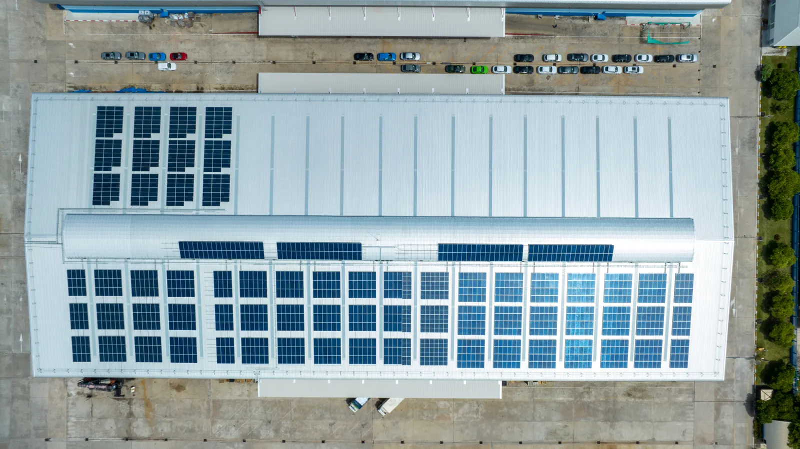
Commercial solar system design determines whether a PV project can meet facility load requirements, pass grid approval, control installation risk, and deliver predictable financial returns. For commercial and industrial projects, design is not simply the process of placing modules on a roof or calculating annual energy output. It is a coordinated engineering, procurement, compliance, construction, and lifecycle asset-management exercise.
For EPCs, installers, system integrators, resellers, facility managers, and commercial project owners, the quality of the design affects almost every downstream outcome. It influences inverter architecture, cable routing, structural loading, grid interconnection, monitoring capability, maintenance access, warranty exposure, and the ability to expand the system later. A layout that looks efficient on paper may create roof access problems, excessive clipping, export curtailment, difficult commissioning, or poor serviceability if system-level decisions are not made early.
This guide approaches commercial PV system design from a B2B and project-delivery perspective. It focuses on the decisions that determine feasibility, compliance, installation quality, operational reliability, and commercial solar ROI from concept through long-term operation.
Commercial solar system design includes far more than module selection and array layout. A complete design process begins with load analysis, tariff review, site assessment, structural evaluation, electrical capacity checks, and project objective definition. It then moves into solar array sizing, inverter selection, mounting design, DC and AC electrical layouts, grid interconnection requirements, safety compliance, monitoring configuration, commissioning planning, and O&M strategy.
For an EPC or installer, design is also a risk-control process. A well-developed design reduces uncertainty in procurement, labor planning, permitting, equipment delivery, construction sequencing, and commissioning. It gives the project team a common technical basis for pricing, installation methods, utility applications, warranties, and performance expectations.
In commercial projects, small design omissions can become expensive. If the roof structure is not confirmed early, the selected mounting system may need to change. If transformer limits are ignored, the system may be forced into export limitation or downsized after procurement. If monitoring is treated as an afterthought, fault detection and performance guarantees become harder to manage. The design phase is therefore where the project’s technical and financial risk profile is shaped.
Before detailed engineering begins, critical feasibility risks must be checked. These “fatal-flaw” items determine whether the project is viable at all.
| Check item | Por que é importante | Typical risk if ignored | Who validates it |
|---|---|---|---|
| Roof remaining life | Avoids reinstall cost | PV removal during roof replacement | Owner / structural engineer |
| Structural reserve capacity | Ensures load safety | Roof overload or redesign | Structural engineer |
| Utility export permission | Confirms grid feasibility | Full export rejection | Utility / EPC |
| Switchboard upgrade need | Impacts electrical scope | Unexpected retrofit cost | Electrical engineer |
| Transformer reverse flow limit | Prevents export blockage | Forced system curtailment | Utility / EPC |
| Roof access safety conditions | Ensures maintenance safety | O&M restrictions | EPC / safety officer |
| Ground-mount permitting risks | Avoids legal delays | Project cancellation | Authority / developer |
| Shutdown constraints | Defines tie-in feasibility | Commissioning delays | Facility manager |
Before selecting equipment, the design team must define what the commercial PV system is expected to achieve. Different facility types lead to different design priorities, such as factories focused on daytime self-consumption, warehouses with low or uneven load profiles, schools with seasonal usage, retail buildings with tenant metering complexity, or industrial sites requiring backup capability for critical operations.
If the objective is energy cost reduction, the system should align PV generation with the facility’s load profile and tariff structure. When demand charge reduction or peak shaving is required, battery storage and load control strategies should be evaluated at the same design stage rather than treated as later additions.
If export revenue is part of the business case, grid capacity, metering requirements, export compensation rules, and curtailment risk must be validated early because they directly affect system sizing and financial performance.
If resilience is required, the system shifts from a standard grid-tied PV design to a backup-capable or hybrid architecture. Grid-tied PV systems are designed to shut down during outages for safety reasons and cannot power onsite loads without additional equipment.
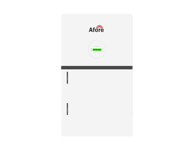
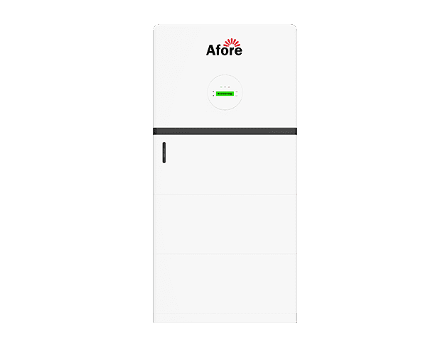
A backup-capable system typically requires island-capable inverters, a critical loads panel, and a transfer switching system, often integrated with battery storage or generator backup. These components enable operation during outages, but they must be designed as a coordinated system rather than individual add-ons.
Load prioritization is a key design requirement in backup systems. Critical loads such as safety systems, IT infrastructure, refrigeration, or selected production lines must be separated from non-critical loads to ensure stable operation during islanded conditions.
In hybrid configurations, PV, batteries, and generators must be coordinated. Batteries typically handle fast response and load balancing, generators provide longer-duration support, and PV follows available generation but may be curtailed depending on system conditions.
Most PV systems cannot restart a dead grid without external support. Black-start capability requires either a battery system or generator to establish initial voltage and frequency before the system can reconnect or operate in island mode.
The key design principle is that maximum kWp is not always the optimal target. The best system is the one that delivers the highest lifecycle value within electrical, operational, and grid constraints.
Site constraints should be mapped before the design team commits to modules, inverters, racking, or storage architecture.
Electrical infrastructure constraints are especially important because they often determine whether PV capacity must be capped or whether upstream equipment upgrades are required.
Electrical upgrade decisions must consider transformer capacity, switchgear limits, and export constraints together.
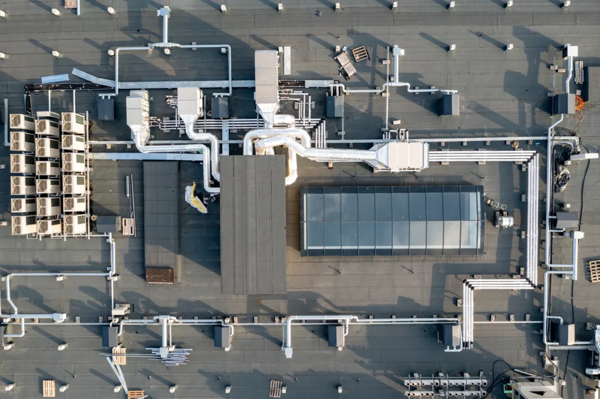
Transformer upgrades are required when reverse power flow exceeds thermal limits or causes unacceptable voltage rise. If grid rules allow export limitation, capping export through EMS may avoid transformer replacement.
A dedicated PV switchboard is recommended when:
Main breaker derating and busbar thermal checks are required when PV backfeed approaches electrical infrastructure limits, especially in older buildings not designed for bidirectional flow.
AC-coupled storage can absorb excess PV generation and reduce peak export, allowing electrical upgrades to be deferred in some cases.
Electrical upgrades and PV system sizing are directly linked.
A larger PV system may appear financially superior initially. However, when transformer replacement, switchgear upgrades, protection relay coordination, and utility interconnection costs are included, the optimal system size may be smaller.
Lifecycle cost evaluation must include electrical infrastructure upgrades, not PV CAPEX alone.
Commercial solar design usually involves multiple stakeholders with different priorities. The building owner may focus on return on investment and roof warranty. The facility manager may care about access, shutdown windows, safety, and operational disruption. The EPC is responsible for deliverability, code compliance, procurement, and installation quality. The utility or grid operator evaluates interconnection, export limits, protection settings, and power quality. The authority having jurisdiction reviews building, electrical, structural, and fire safety compliance. Financiers and insurers may impose additional requirements related to equipment certification, performance modeling, warranties, and asset risk.
A strong design process clarifies who approves each decision and when. For example, the owner may approve the business case at concept stage, the structural engineer may approve roof loading before procurement, the utility may approve interconnection before construction, and the O&M provider may review monitoring and access provisions before final design. This responsibility allocation reduces delays and prevents late-stage conflicts between commercial, technical, and regulatory requirements.
Commercial solar system sizing starts with interval load data, utility bills, tariff structure, site capacity, interconnection limits, and project objectives. In real projects, data quality varies, so engineers must also correct abnormal periods such as shutdown months, seasonal production drops, or temporary operational changes before using annual consumption for sizing decisions. Unlike many residential projects, C&I solar installation size is often constrained by roof or land availability, export limits, transformer capacity, budget, and target payback period rather than annual consumption alone.
The design team should ideally review at least 12 months of electricity bills and interval data, preferably in 15-minute, 30-minute, or hourly resolution. This data shows total energy use, peak demand timing, and seasonal load patterns, and it helps determine how much PV energy can be self-consumed or exported.
In practice, different facility types require different corrections:
This step improves sizing accuracy and reduces oversizing risk in commercial PV projects.
A practical sizing process usually starts with a technical maximum, then narrows the system based on economic and interconnection constraints. When interval load data is missing or unreliable, EPCs should use temporary monitoring or submetering before final system sizing. This is especially important for multi-tenant buildings, industrial facilities with variable production, or sites with incomplete utility records. Short-term measurement improves accuracy and reduces oversizing risk.
The designer estimates how much PV capacity can physically fit, models annual production, compares generation against load, checks grid export rules, and evaluates financial performance under different system sizes. The final system size should be justified by both engineering feasibility and commercial value.
Commercial tariffs are often more important than total energy consumption in commercial solar design. Many facilities are billed not only for kilowatt-hours but also for peak demand charges, time-of-use pricing, power factor penalties, contracted capacity, or ratchet-based demand structures.
Because of this, PV systems should be evaluated against peak demand timing rather than annual energy reduction alone. A system that aligns with daytime peaks can deliver higher financial savings than a larger system that exports excess energy during low-value periods.
Storage feasibility should also be screened at this stage because it is tightly linked to peak demand reduction and export limitation strategies. Early evaluation ensures PV and storage are modeled together rather than treated as separate design decisions.
To reflect real operating conditions, load profiles should be normalized before sizing. This removes temporary shutdowns, seasonal production changes, and one-off operational anomalies that can distort annual consumption data.
Typical commercial profiles vary significantly. A refrigerated warehouse may have stable 24-hour demand, while a manufacturing facility may operate only one daytime shift, creating strong weekday alignment but low weekend utilization. Schools and retail buildings often show strong daytime load during specific periods but large seasonal variation.
For EPCs, PV generation should always be compared against the actual load curve rather than total annual consumption. When load and generation are poorly aligned, smaller systems, export control, demand management strategies, or storage integration may produce better lifecycle value than simply increasing installed capacity.
Two common sizing approaches should be distinguished: annual offset sizing and daytime minimum-load sizing. Annual offset aims to maximize yearly energy coverage, while minimum-load sizing focuses on avoiding export and curtailment risk by limiting PV output to daytime demand levels.
For zero-export systems, PV capacity must be limited to on-site daytime consumption to prevent reverse power flow. Partial-export systems allow higher capacity but require export control systems and curtailment logic. These constraints directly affect inverter loading strategy and final system size.
Annual yield estimates drive commercial solar ROI, financing assumptions, and performance guarantees. When export is capped or remote curtailment is likely, production modeling must separate clipped energy and curtailed energy from usable on-site consumption. This distinction is important because curtailed energy does not contribute to revenue, since it is not delivered as usable AC energy to the facility or the grid, even though it irepres ents potentilal generategy production at the DC array level. Key performance metrics include specific yield, performance ratio, soiling losses, shading losses, temperature losses, wiring losses, inverter losses, clipping losses, availability, and annual module degradation. For professional projects, these assumptions should be transparent and documented.
Typical commercial PV performance varies by climate, system orientation, module technology, design quality, and O&M. Yield modeling should use credible irradiance datasets, site-specific shading, realistic temperature assumptions, and conservative loss factors. Public tools and government datasets can support early-stage modeling, while bankable projects usually require more detailed simulation and engineering review. Based on the NREL PVWatts solar calculator, early-stage commercial solar system design commonly uses standardized irradiance and performance assumptions to benchmark annual energy yield before detailed site-specific simulation is conducted.
A concise set of performance assumptions helps decision-makers compare scenarios clearly.
| Métrico | Typical commercial design consideration |
|---|---|
| Rendimento específico | Annual kWh produced per installed kWp, highly location-dependent |
| Índice de desempenho | Often around 0.75–0.85 for well-designed systems, depending on losses |
| Soiling loss | Commonly 2–10%, depending on dust, pollution, rainfall, and cleaning |
| DC/AC ratio | Often above 1.0 to improve inverter utilization |
| Degradação do módulo | Commonly modeled annually over 25–30 years |
| Disponibilidade | Critical for financial modeling and O&M performance guarantees |
These metrics should not be treated as generic defaults. A dusty industrial site, coastal environment, high-temperature roof, or heavily obstructed rooftop requires different assumptions from a clean, open, well-ventilated ground-mounted array.
Commercial PV systems often use a DC/AC ratio above 1.0, meaning the DC module capacity is greater than the inverter AC output capacity. This can improve inverter utilization during morning, afternoon, and lower-irradiance periods. However, excessive oversizing can increase clipping losses, thermal stress, and curtailment, especially where export limits already restrict AC output.
The optimal DC/AC ratio depends on local irradiance, module orientation, inverter cost, AC connection limits, tariff value, and acceptable clipping. East-west rooftop layouts may support different inverter loading strategies from south-facing arrays. Sites with export caps may need careful modeling to avoid installing DC capacity that cannot be economically used. The best design is not necessarily the one with the least clipping; it is the one where additional DC capacity produces enough valuable energy to justify its cost.
Commercial solar system design often begins by comparing where the PV array should be installed. Rooftop systems are common because they use underutilized building space and usually connect behind the meter.
Commercial rooftop PV layout must account for multiple physical and regulatory constraints that reduce usable installation area.
Unusable edge zones are typically required due to wind uplift forces, which are higher at roof corners and perimeter areas. These zones reduce effective installation area even when roof space appears sufficient on drawings.
Drainage paths must remain unobstructed to prevent ponding and water accumulation. PV rows must be positioned to avoid blocking primary and secondary drainage routes, especially on low-slope industrial roofs.
Roof membrane compatibility must also be evaluated before selecting mounting systems. Ballasted systems are typically preferred for single-ply membranes, while mechanically attached systems may be required for structural or wind load reasons.
Many roof manufacturers impose warranty restrictions on penetrations. PV mounting design must be coordinated with the roof warranty provider to avoid voiding membrane warranties.
HVAC units, skylights, and service access lanes must remain accessible. PV layouts must preserve maintenance routes and future equipment replacement paths, not only current clearance conditions.
Ballast systems may introduce slip risk on smooth or aged roof finishes. Anti-slip layers or mechanical restraints may be required depending on roof surface conditions.
Wind uplift varies by roof zone. Edge and corner areas experience significantly higher loads than central zones, requiring higher attachment density and zone-based racking design.
Attachment spacing must therefore vary according to wind zone, roof height, and local code requirements.
A structured obstruction mapping process should be used:
However, they are constrained by roof condition, structural capacity, access, and fire pathways. Ground-mounted systems can provide more layout flexibility and easier maintenance but require land, civil works, fencing, permitting, and longer cable runs. Solar carports can make productive use of parking areas while offering shading benefits, but they involve steel structures, foundations, drainage, lighting, traffic coordination, and often higher CAPEX.
| Installation type | Best suited for | Main design constraints |
|---|---|---|
| Flat-roof PV | Warehouses, factories, retail buildings | Ballast, wind uplift, roof membrane, access paths |
| Penetrating roof mount | Metal roofs or structurally suitable roofs | Waterproofing, attachment points, roof warranty |
| Ground-mounted PV | Industrial campuses, land-rich facilities | Land use, geotechnical design, fencing, drainage |
| Solar carport | Offices, retail, logistics parking areas | Foundations, vehicle clearance, civil works, cost |
| Degradação do módulo | Commonly modeled annually over 25–30 years | |
| Disponibilidade | Critical for financial modeling and O&M performance guarantees |
Many commercial projects combine multiple formats. A manufacturing campus, for example, may use rooftop PV for self-consumption, carports for employee parking, and a ground-mounted array for expansion capacity. The design should compare lifecycle value, not just installed cost per watt.
Shading analysis is central to commercial solar array sizing and layout. Commercial rooftops often contain HVAC units, skylights, vents, parapets, antennas, signage, and nearby buildings. Even partial shading can reduce string performance, create mismatch losses, and complicate inverter MPPT design.
Tilt and azimuth decisions involve trade-offs. Low-tilt systems on flat roofs can increase installed capacity per square meter and reduce wind loading, but may increase soiling and reduce self-cleaning. Higher tilt can improve winter production and drainage but increases row spacing and wind exposure. East-west layouts can produce a broader generation curve and fit more modules on some flat roofs, while south-facing layouts may maximize annual yield per module in many northern hemisphere locations.
Row spacing should consider sun path, inter-row shading, maintenance walkways, fire access, and wind zones. The design should also account for future shading growth from vegetation, new equipment, building extensions, or adjacent development. For EPCs, shading assumptions must be documented because they directly affect production estimates and performance guarantees.
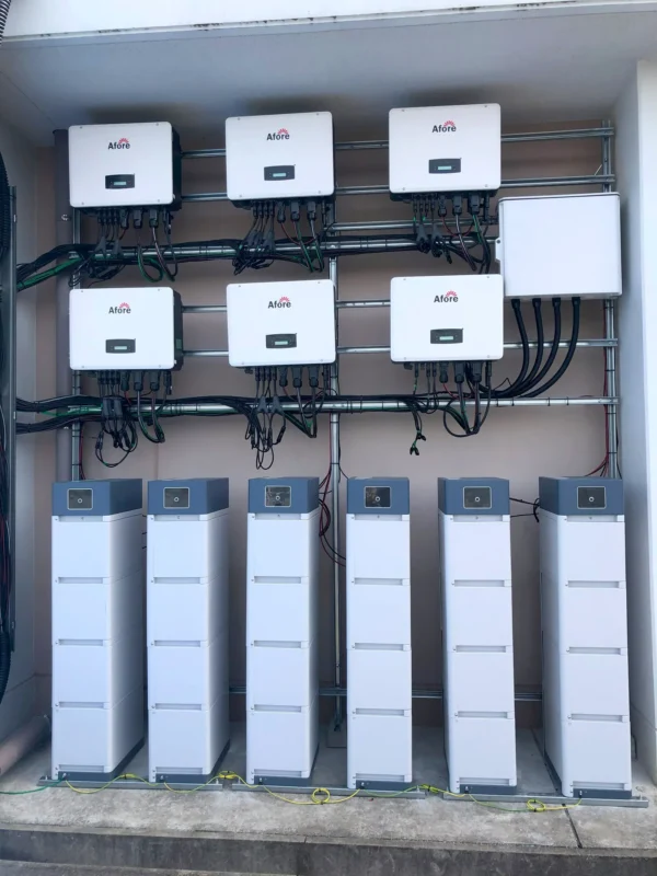
Structural review is a non-negotiable part of commercial PV system design. Rooftop arrays add dead load, wind uplift forces, and in some climates snow-load interactions. Ballasted systems can reduce roof penetrations but may add significant distributed weight. Penetrating systems can reduce ballast but introduce waterproofing and warranty considerations. Edge and corner zones often experience higher wind uplift, which affects racking layout and attachment design.
Roof lifecycle planning is equally important. Many PV systems are expected to operate for 25 years or more, while commercial roof membranes may have shorter remaining life. Installing PV on a roof that will need replacement in five years can create major future costs because the array may need to be removed and reinstalled. Facility owners should coordinate roof inspection, warranty review, and replacement planning before approving the PV project.
Single-line diagrams are the foundation of commercial PV electrical documentation. They show how modules, strings, inverters, combiner boxes, protection devices, disconnects, meters, switchgear, transformers, and utility interfaces connect. Accurate single-line diagrams support permitting, procurement, installation, commissioning, troubleshooting, and future expansion.
Detailed electrical documentation should also include string diagrams, cable schedules, grounding and bonding details, protection settings, labeling plans, equipment datasheets, monitoring architecture, and metering configuration. For larger C&I systems, the design may also require short-circuit studies, voltage rise calculations, power quality analysis, protection coordination, and utility-approved relay settings.
PV module selection should consider more than price per watt. Commercial buyers and EPCs should evaluate module efficiency, power class, temperature coefficient, degradation warranty, product warranty, mechanical load rating, fire classification, electrical characteristics, certification, packaging, transport risk, supplier stability, and long-term availability.
High-efficiency modules can be valuable where roof area is limited, but larger-format modules may affect handling, racking compatibility, wind loading, and installation labor. Temperature coefficient matters on hot rooftops because elevated cell temperature reduces output. Mechanical load rating matters in snow, wind, and hail-prone regions. Warranty terms matter, but so does the practical ability to process claims and obtain replacements years after installation.
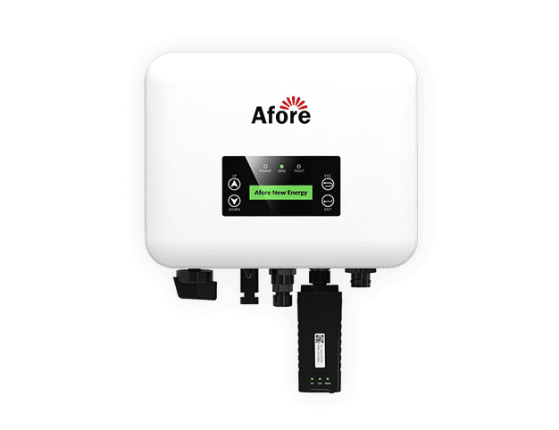
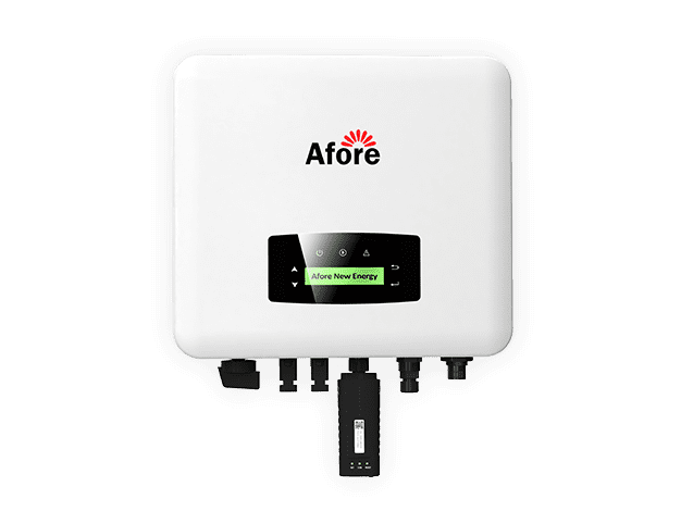
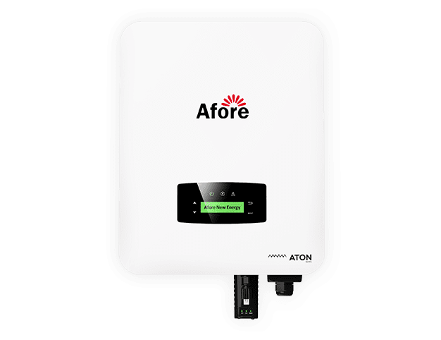
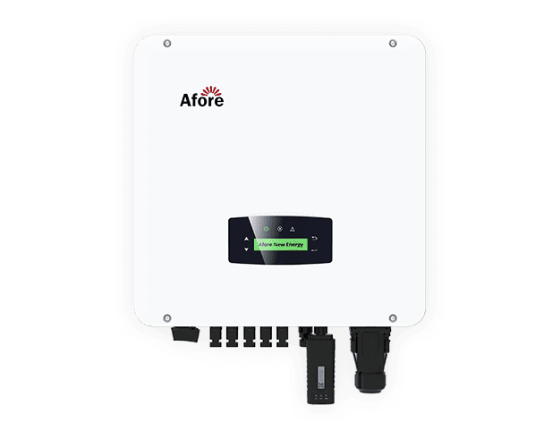
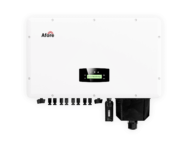
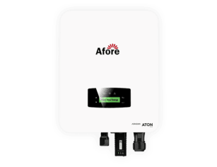
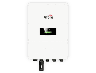
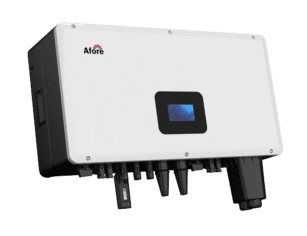
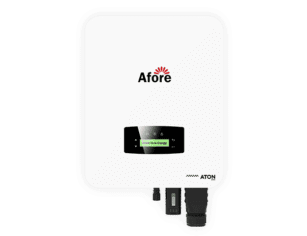
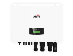
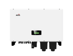
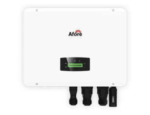
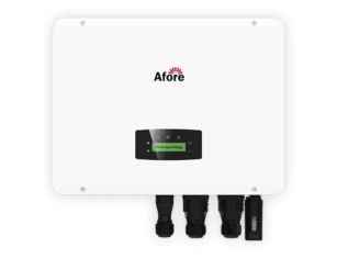
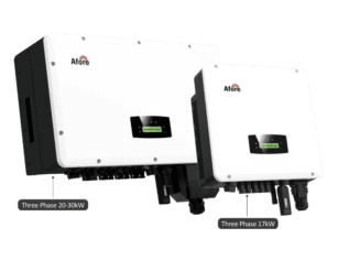
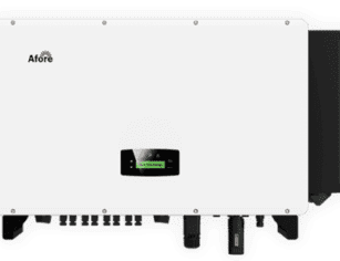
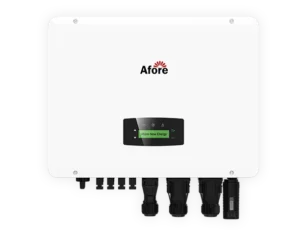
PV inverter selection shapes system architecture, redundancy, monitoring granularity, and maintenance strategy, especially when inversores solares híbridos are used for storage integration and backup-capable commercial systems. Commercial projects increasingly use three-phase string inverters because they offer modularity, design flexibility, and partial redundancy. If one inverter fails, only part of the system is affected. String inverters can also simplify phased installation and provide more granular performance data.
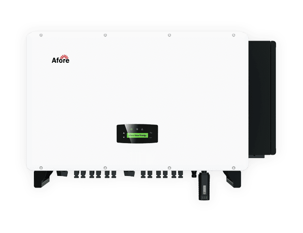
Central inverters may be suitable for larger ground-mounted systems or projects where centralized equipment, medium-voltage integration, and utility-style design are preferred. They can reduce the number of inverter units but may concentrate downtime risk and require more specialized service access.
Module-level power electronics may be useful where shading is complex, where module-level monitoring is required, or where rapid shutdown rules apply. However, they add components to the roof and must be evaluated for reliability, serviceability, compatibility, and cost. The right architecture depends on site conditions, local safety rules, O&M strategy, and commercial objectives.
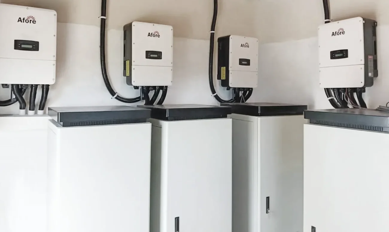
Balance-of-system components include mounting structures, DC and AC cables, connectors, combiner boxes, junction boxes, breakers, disconnects, switchgear, transformers, meters, data acquisition systems, and monitoring devices. BOS quality has a major impact on installation labor, electrical losses, downtime, safety, and long-term service cost.
Connector mismatch, poor cable management, underspecified switchgear, unsuitable cable trays, or low-quality enclosures can create failures that are expensive to diagnose and repair. For EPCs and resellers, procurement should evaluate certification, compatibility, lead time, warranty support, and field-proven performance. A low-cost BOS package can become expensive if it causes rework, delays grid approval, or increases O&M callouts.
Commercial PV design should verify full-system compatibility before procurement. String voltage must remain within inverter limits under cold and hot operating conditions. Module current must be compatible with inverter input limits and protection devices. Communication protocols must support monitoring, export control, storage integration, and energy management requirements. Rapid shutdown devices, if required, must be compatible with modules and inverters.
Based on IEC 62548 PV array design standard, commercial solar system design must ensure that string voltage limits, current ratings, and DC system configurations remain within safe operating boundaries under all environmental conditions. Local codes and utility rules may impose additional requirements, so compliance must be checked for the specific market and site.
Commercial solar permits vary by country, region, utility, and authority having jurisdiction. Typical approvals may include building permits, electrical permits, structural review, fire safety review, environmental review for ground-mounted systems, utility interconnection approval, metering approval, and final inspection sign-off.
The permitting process should be built into the project schedule. A technically complete design package helps reduce review cycles because it gives authorities clear evidence of structural adequacy, electrical safety, equipment certification, fire access, and grid compliance. For EPCs, missing documentation is one of the most common causes of permitting and commissioning delay.
Utility interconnection can determine the final system size and operating mode. The utility may review transformer capacity, feeder hosting capacity, voltage rise, reverse power flow, protection settings, anti-islanding functions, metering arrangements, and export limits. Larger commercial systems may require grid studies, external protection relays, remote disconnect capability, or specific inverter functions.
Some projects are allowed full export. Others are approved only with limited export or zero-export control. Export-limited systems require reliable metering and control logic to prevent reverse power beyond the approved threshold. If curtailment is expected, it must be included in the energy model and financial case. A project that looks attractive under unlimited export may fail its return targets if grid constraints force frequent curtailment.
Grid codes are becoming more demanding for distributed generation, especially around voltage support, frequency response, ride-through behavior, and active power control. In the European context, commercial solar system design must comply with grid interconnection requirements defined under EU Electricity Network Codes, which establish technical rules for system stability, voltage control, and grid connection behavior. Detailed information on these network code frameworks is published by the European Commission.
An export-limited PV system must be defined as a complete control and compliance package, not just a software setting. The design documentation should clearly specify:
Without these definitions, export-limited systems can fail during commissioning, witness testing, or real operating conditions even if the hardware is correctly sized.
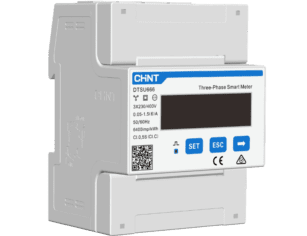
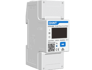
Zero-export and export-limited systems require active control of PV output based on real-time site demand. The architecture typically includes revenue-grade meters, a controller or EMS, and inverter communication interfaces.
There are two main control approaches:
EMS-based systems offer more flexibility, especially when storage or multiple loads are involved, while inverter-native control is simpler but less adaptable.
Revenue-grade meters are typically installed at the point of interconnection (POI), usually on the main utility feed or main distribution board. This ensures export is measured at the correct boundary and aligns with utility requirements.
Incorrect meter placement can lead to export violations or failed interconnection approval, even if PV generation is technically within limits.
Export control systems must respond fast enough to prevent reverse power flow. Typical response times range from sub-second to a few seconds depending on inverter type and communication architecture.
Slow response can cause short-term export spikes, which may violate utility limits even if average export is compliant.
System stability also depends on filtering logic to avoid oscillation when load fluctuates rapidly.
If communication between meters, EMS, and inverters is lost, the system must default to a safe operating mode.
Common fail-safe strategies include:
Fail-safe design is critical for compliance approval in many utilities.
Many utilities require on-site witness testing before granting final interconnection approval. This typically includes:
Failure during witness testing is a common cause of commissioning delay.
When storage is included, curtailment priority must be clearly defined:
Without a defined hierarchy, systems may behave unpredictably during high generation periods.
Commercial PV systems must be designed for electrical safety, fire service access, emergency isolation, grounding and bonding, overcurrent protection, labeling, and safe maintenance. Requirements vary by jurisdiction, but the design should address DC disconnects, AC isolation, inverter placement, cable routing, equipment clearances, protection devices, arc-fault requirements where applicable, and rapid shutdown where required.
Fire access requirements can significantly reduce usable roof area. Setbacks, pathways, smoke ventilation access, and clear routes to roof hatches or service equipment must be considered before finalizing the module layout. This is why early site surveys should capture not only available roof area but also code-required access zones.
Larger C&I solar systems can affect site electrical behavior. Designers may need to evaluate voltage rise, harmonics, flicker, power factor, short-circuit current, reverse power flow, and coordination with existing protection devices. In weak grids or congested feeders, the utility may require inverter settings for reactive power control, export limitation, voltage-watt response, or remote curtailment.
Protection coordination is especially important where PV connects to existing industrial switchgear. The design should ensure that faults are cleared safely and selectively, without creating nuisance trips or compromising facility operations. For critical facilities, shutdown sequencing and interaction with backup generators or UPS systems should be reviewed carefully.
Commercial installations often take place on active facilities. The design should support efficient construction while minimizing disruption to operations. EPCs need to plan equipment delivery, staging areas, crane access, roof loading during construction, temporary safety zones, cable routes, electrical shutdown windows, and coordination with facility staff.
A good design anticipates installation realities. Inverter locations should allow safe access and ventilation. Cable trays should be serviceable and protected. Roof walkways should support both construction and future maintenance. Equipment should be staged without exceeding roof load limits. If the facility operates continuously, electrical tie-ins may need to occur during planned shutdowns or off-hours.
Commissioning verifies that the installed system matches the approved design and performs safely. Typical commercial PV commissioning includes visual inspection, torque verification, polarity checks, insulation resistance testing, string voltage checks, current verification, IV curve testing where specified, inverter startup, protection device checks, metering validation, monitoring verification, export control testing, and review of as-built documentation.
Commissioning is not a paperwork exercise. It is the transition from construction project to operating asset. Errors found during commissioning, such as incorrect stringing, reversed polarity, communication faults, or improperly configured inverter settings, are easier to correct before final handover than after the system is energized and expected to generate revenue.
Several recurring installation risks can reduce performance or increase O&M costs. Connector mismatch can lead to overheating and failure. Poor cable management can cause abrasion, water exposure, or damage from wind movement. Inadequate roof protection can damage membranes and create leak claims. Insufficient inverter ventilation can reduce output or shorten equipment life. Incorrect labeling can slow emergency response and maintenance. Uncontrolled shading changes can invalidate production assumptions.
For installers and EPCs, quality assurance should be embedded into construction, not added only at the end. Field teams should work from approved drawings, maintain change logs, document deviations, and capture photographic records of critical details before they are concealed.
A commercial PV handover package should include as-built drawings, single-line diagrams, string maps, equipment datasheets, warranty documents, commissioning reports, monitoring access credentials, maintenance procedures, emergency shutdown instructions, inspection records, spare parts lists, and utility approval documents.
This documentation has long-term value. It helps O&M teams troubleshoot faults, supports warranty claims, assists insurers and financiers, and reduces downtime when equipment needs replacement. For multi-site owners, standardized handover documentation also makes portfolio management significantly easier.
Commercial solar performance risk continues after commissioning. Soiling, new shading, inverter downtime, module degradation, connector failures, water ingress, grid outages, communication faults, thermal stress, roof maintenance, and accidental damage can all reduce production.
Design choices influence how easily these issues are detected and corrected. Systems with strong monitoring, accessible equipment, documented string maps, and safe maintenance pathways can be operated more efficiently. Systems with poor access, unclear labeling, or limited data may suffer extended downtime because faults are harder to locate.
Monitoring should be designed around the commercial importance of the asset. Basic inverter monitoring may be sufficient for smaller systems, but larger commercial portfolios often require revenue-grade metering, weather sensors, string-level data, automated fault alerts, performance benchmarking, and centralized dashboards.
Performance analytics allow O&M providers to compare actual output against expected production. If a system underperforms, data can help determine whether the cause is soiling, shading, inverter faults, grid curtailment, or sensor error. For EPCs offering performance guarantees, monitoring architecture must be robust enough to support contractual reporting.

Preventive maintenance typically includes visual inspections, thermographic inspections, electrical testing, cleaning strategy review, vegetation control for ground-mounted systems, inverter maintenance, mounting structure checks, drainage review, and monitoring system verification. The appropriate schedule depends on site conditions, climate, equipment type, and contractual obligations.
Designing for service access reduces lifecycle cost. Technicians need safe routes, working clearances, clear labeling, accessible inverters, and well-managed cables. A system that maximizes module density but makes maintenance difficult may lose value over time through higher labor cost and longer outages.
Commercial PV warranties may cover modules, inverters, mounting systems, workmanship, monitoring hardware, and system performance. However, warranty value depends on claim processes, local service capability, response times, documentation quality, and spare parts availability.
EPCs and resellers should evaluate supplier support as part of procurement. For repeat commercial deployments, standardizing equipment families can reduce spare parts complexity and improve service response. Inverter replacement planning is especially important because inverter lifetimes and warranty periods may be shorter than module performance warranty periods.
Commercial solar ROI is calculated from installed cost, annual energy yield, electricity tariff savings, demand charge reduction, incentives, export compensation, O&M cost, financing terms, degradation, tax treatment, insurance, inverter replacement, and expected system life. The calculation should reflect the actual operating strategy of the system, not only its nameplate capacity.
For behind-the-meter projects, self-consumed solar energy usually has higher value than exported energy when retail electricity rates exceed export compensation. Demand charge savings may be valuable but are often less predictable unless PV output reliably coincides with billing peaks or storage is included. For export-oriented projects, grid approval, metering rules, and curtailment risk become central to the financial model.
Commercial PV CAPEX includes modules, inverters, mounting structures, BOS components, engineering, permitting, labor, electrical upgrades, interconnection, monitoring, contingency, and project management. OPEX includes cleaning, inspections, corrective maintenance, monitoring subscriptions, insurance, vegetation control where applicable, and inverter replacement reserves.
| Financial metric | What it tells decision-makers |
|---|---|
| Simple payback | How many years until cumulative savings recover upfront cost |
| Net present value | Lifecycle value after discounting future cash flows |
| Internal rate of return | Investment return compared with alternative uses of capital |
| LCOE | Average cost of generated solar energy over system life |
| Disponibilidade | Revenue impact of downtime and O&M effectiveness |
A lower upfront cost does not always produce the best lifecycle economics. If cheaper equipment increases downtime, warranty risk, electrical losses, or maintenance labor, the project’s levelized cost of energy may worsen.
Design choices have direct financial consequences. Higher-efficiency modules may increase capacity on space-constrained rooftops. A better DC/AC ratio may improve inverter utilization. A more robust mounting system may reduce roof risk and insurance concerns. String inverter architecture may reduce downtime exposure. Strong monitoring may improve availability and support performance guarantees.
Conversely, poor design decisions can undermine financial returns. Oversizing without considering export limits can lead to curtailment. Ignoring roof lifecycle can create removal and reinstallation costs. Selecting incompatible components can delay commissioning. Underestimating soiling can overstate revenue. Treating O&M as a post-installation issue can increase lifecycle cost.
Procurement should support both project delivery and long-term asset performance. EPCs, installers, and resellers should evaluate product certification, compatibility with local grid requirements, supply continuity, lead times, logistics, warranty terms, documentation quality, technical support, and replacement availability.
For multi-site commercial deployments, approved equipment lists and standardized design templates reduce engineering time and procurement risk. However, standardization should not override site-specific constraints. The best procurement strategy balances repeatability with engineering flexibility.
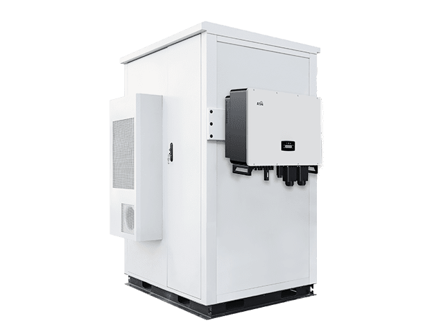
Battery storage should be considered when the facility has high demand charges, time-of-use tariffs, low self-consumption, export limitations, resilience requirements, or a need to manage peak loads. Storage can increase self-consumption, reduce demand peaks, support backup power, and help comply with export limits.
However, storage should not be added automatically. The business case depends on load profile, tariff structure, battery cycling strategy, control accuracy, available space, safety requirements, and local regulations. A battery sized for peak shaving is different from one sized for backup duration. A battery intended to manage export caps needs fast and reliable control integration with PV inverters and site meters.
Storage and backup feasibility should be screened at the same time as PV sizing because they directly affect system architecture, inverter selection, and interconnection constraints. Commercial facilities increasingly need to plan for EV chargers, electrified processes, heat pumps, battery energy storage systems, backup generators, and microgrid controls. Future-ready commercial solar system design reserves electrical capacity, communication pathways, physical space, and monitoring scalability.
If backup power is required, designers must define critical loads, islanding capability, transfer switching, black-start requirements, generator coordination, and battery operating modes. Standard grid-tied PV inverters usually shut down during outages unless they are part of an approved hybrid or microgrid system. This distinction must be clear to owners who expect resilience benefits.
For resellers, EPCs, and multi-site commercial owners, portfolio standardization can reduce engineering time, procurement complexity, training needs, and O&M cost. Standard design templates, approved equipment families, repeatable commissioning procedures, common monitoring platforms, and consistent documentation formats improve scalability.
A retailer with 100 sites, for example, may classify buildings into small rooftop, large rooftop, carport, and constrained-grid archetypes. Each archetype can use a standard design basis while allowing site-specific adjustments for structure, shading, interconnection, and tariffs. This approach supports faster deployment without sacrificing engineering control.
Future expansion should be considered during initial design. Oversized conduits, reserved switchgear space, scalable monitoring, transformer capacity planning, and spare communication ports can reduce future upgrade costs. Even if storage or EV charging is not included initially, the PV design can avoid blocking those upgrades.
Expansion planning is particularly important for facilities expecting load growth, electrification, production changes, or corporate decarbonization targets. A slightly higher upfront investment in electrical infrastructure may be justified if it avoids expensive rework later.
A professional design process should move through clear decision gates. At concept stage, define the project objective, collect load and tariff data, assess site constraints, and confirm ownership, financing, and stakeholder approvals. During preliminary design, estimate installable capacity, model production, compare system architectures, check interconnection feasibility, and build an initial financial case. During detailed design, finalize equipment selection, structural calculations, electrical diagrams, protection strategy, monitoring architecture, and permitting documents. Before construction, verify procurement, installation sequencing, shutdown windows, quality plans, and commissioning procedures. At handover, provide complete as-built documentation and establish O&M responsibilities.
The strongest commercial PV projects are not designed around a single metric such as lowest CAPEX, highest kWp, or shortest payback. They are designed as long-life energy assets that must operate safely, comply with grid and building requirements, produce predictable energy, and remain serviceable for decades.
The first step is defining project goals and collecting feasibility data before selecting any equipment. This includes interval load data, tariff structure, roof or land constraints, electrical infrastructure, and grid interconnection requirements. These inputs determine whether the project is technically and economically viable. Equipment selection should only happen after this screening stage.
System size should be based on usable installation area, daytime load profile, tariff structure, export limits, transformer and switchgear capacity, and financial targets. In most cases, the optimal size is not the maximum kWp that can physically fit. The best system is the one that delivers the highest lifecycle value under electrical and grid constraints. Oversizing without considering constraints can reduce ROI.
Commercial solar projects typically require building permits, electrical permits, structural signoff, and fire safety review from the authority having jurisdiction (AHJ). Utility interconnection approval is a separate process that evaluates grid impact and export conditions. Ground-mounted systems may also require civil, drainage, land-use, or environmental approvals. Requirements vary by jurisdiction and utility rules.
No, storage is not always required and should be modeled rather than assumed. It is typically used for peak shaving, backup power, export control, or time-of-use arbitrage depending on project goals. Each use case requires different sizing and control strategies. Storage should be evaluated during design, not added after PV sizing.
The main ROI drivers are self-consumption rate, interconnection limits, and usable energy delivered to the facility. Tariff structure, including energy and demand charges, strongly affects savings potential. Downtime, maintenance access, and system reliability also impact long-term returns. The best ROI comes from balancing energy value and lifecycle risk, not just CAPEX.








 Turkish
  Romanian