


A 48v 200ah lifepo4 battery is one of the most common low-voltage storage modules used in solar PV systems, telecom backup, remote power, and small commercial energy storage. On paper, the calculation looks simple: 48 volts multiplied by 200 amp-hours equals 9.6 kWh of nominal energy. In practice, many LiFePO4 battery packs are built around a 51.2V nominal architecture using 16 cells in series, giving a nominal capacity of about 10.24 kWh.
For EPCs, installers, resellers, and commercial PV buyers, however, nominal capacity is only the starting point. The real question is not only the nominal capacity, but whether the battery system is properly matched to the overall electrical design of the project.
A 48V 200Ah lithium iron phosphate battery can be an effective modular building block for PV storage, but it should not be evaluated as a standalone product. It is part of a complete electrical, thermal, communications, protection, and commercial system. A well-selected battery can reduce truck rolls, improve backup reliability, and support solar self-consumption. A poorly matched battery can create nuisance shutdowns, warranty disputes, capacity shortfalls, or permitting delays.
This guide explains how professional PV stakeholders should evaluate, size, install, operate, and procure a 48V 200Ah LiFePO4 battery for commercial and distributed solar storage applications.
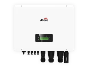
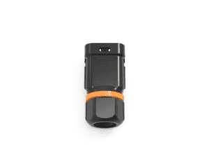
A 48V 200Ah LiFePO4 battery is a rechargeable lithium iron phosphate battery module designed to provide low-voltage DC energy storage. It is commonly used with hybrid inverters, off-grid inverters, telecom rectifier systems, and modular battery cabinets. In PV storage projects, it is usually selected where the system requires manageable installation voltage, modular expansion, and daily cycling capability without the maintenance burden of lead-acid batteries.
The term “48V” is often used as a system class rather than an exact operating voltage. Traditional lead-acid systems were commonly arranged as 48V nominal battery banks, and many solar inverters, telecom systems, and DC power platforms were designed around that architecture. LiFePO4 systems adopted the same market category, but their actual voltage profile differs from lead-acid.
A basic 48V × 200Ah calculation gives 9,600 Wh, or 9.6 kWh. Many modern 48V LiFePO4 battery modules are technically 51.2V nominal because they use 16 LiFePO4 cells in series, each with a nominal voltage of approximately 3.2V. In that case, 51.2V × 200Ah equals 10.24 kWh.
For project design, the more important number is usable AC energy. This depends on the allowed depth of discharge, inverter conversion efficiency, battery reserve settings, BMS limits, and temperature behavior. A 10 kWh-class battery operated at 80% usable depth of discharge may provide around 8 kWh of DC energy before inverter losses. After conversion losses and operational reserve, the delivered AC energy may be closer to 7.2–7.7 kWh.
| Parametru | Typical value for a 48V 200Ah LiFePO4 battery | De ce este important |
|---|---|---|
| Nominal energy | 9.6–10.24 kWh | Base capacity for system sizing |
| Usable DC energy at 80% DoD | 7.7–8.2 kWh | More realistic backup and cycling figure |
| Continuous current | Often 100–200A | Determines usable power, not just energy |
| Approximate continuous power | 5–10 kW depending on BMS | Must match inverter and load demand |
| Typical cycle-life claim | 3,000–6,000 cycles under defined conditions | Must be checked against warranty assumptions |
For commercial backup applications, this distinction is critical. A facility manager may expect “10 kWh” to support a 5 kW critical load for two hours. In reality, after depth-of-discharge limits and inverter losses, that same battery may provide closer to 1.4–1.6 hours unless more modules are installed.
Lithium iron phosphate has become widely used in solar storage because it offers a strong balance of safety, cycle life, efficiency, and operating simplicity. Compared with lead-acid, LiFePO4 batteries generally support deeper usable discharge, higher round-trip efficiency, lower maintenance, and a much longer cycle life in daily cycling applications.
Compared with some other lithium chemistries, LiFePO4 is also valued for thermal stability. This does not mean fire risk can be ignored. It means the chemistry is generally more tolerant and less prone to thermal runaway than higher-energy-density lithium chemistries under comparable abuse conditions. For B2B projects, chemistry is only one part of safety. Buyers still need to verify cell quality, BMS design, enclosure construction, protection coordination, installation conditions, and certifications.
A 48V 200Ah lithium battery is most suitable for distributed and moderate-power applications rather than utility-scale storage. Common commercial and light-industrial use cases include telecom backup, remote monitoring stations, small retail critical-load backup, agricultural PV systems, off-grid site offices, security systems, water pumping control systems, and hybrid solar-plus-storage installations for small business facilities.
In these applications, the battery often supports a clearly defined load rather than an entire building. For example, a shop may use several modules to back up point-of-sale equipment, lighting, networking, refrigeration controls, and security systems during outages. A telecom site may use a battery bank to maintain DC loads during grid interruptions while reducing generator runtime.
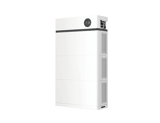
A single 48V 200Ah battery should be understood as a modular storage block, not a complete commercial energy storage solution in most cases. When multiple 48V 200Ah batteries are used in a system, expansion must remain within the manufacturer’s approved parallel connection limit. System scaling should strictly follow the technical requirements defined in the product manual.
In addition, multi-module battery banks require proper communication architecture, correctly designed DC busbars, and coordinated protection devices to ensure stable current sharing and safe operation.
Operating beyond the recommended parallel limit or without proper system design may lead to uneven current distribution, communication instability between modules, and reduced overall system reliability.
One unit may be sufficient for small critical loads, but meaningful commercial backup, peak shaving, or evening load shifting often requires multiple modules in parallel.
A bank of four modules, for instance, creates roughly 40 kWh nominal capacity. This can be appropriate for a small C&I site, a remote telecom hub, or an agricultural system with controlled loads. However, as power and capacity requirements increase, DC current rises quickly in 48V systems. At that point, high-voltage battery platforms may become more efficient and practical.
When reviewing a 48V 200Ah LiFePO4 battery datasheet, EPCs should verify the following parameters in a structured checklist:
Datasheets for 48V LiFePO4 batteries often look similar, but small differences in voltage windows, BMS current limits, communication protocols, thermal controls, and warranty conditions can significantly affect field performance. EPCs should treat the battery datasheet as an engineering document, not just a sales brochure.
The label “48V” must be checked against the actual voltage range. A LiFePO4 battery may operate from the low-40V range when deeply discharged up to the high-50V range when fully charged, depending on the manufacturer’s design and BMS settings. The inverter must be compatible with the full operating voltage window defined by the battery manufacturer.
This is especially important when replacing lead-acid battery banks. A charge profile designed for lead-acid may not be appropriate for lithium iron phosphate. LiFePO4 batteries normally require specific bulk, absorption, float, and low-voltage cutoff settings.
Float voltage settings should always follow the battery manufacturer’s recommended inverter profile rather than generic lead-acid settings. Incorrect float configuration can lead to overcharging or long-term degradation of LiFePO4 cells.
In practice, some LiFePO4 battery systems use a reduced float voltage, while others recommend disabling float charging entirely. In these cases, the inverter may switch to a standby or maintenance voltage mode instead of maintaining a continuous float stage.
The correct approach depends on the specific BMS and inverter pairing, and should always be validated using the manufacturer’s configuration guide.
In many lithium systems, float is reduced or disabled because long-term high state of charge can accelerate calendar aging.
Amp-hours describe energy capacity, not power capability. A 200Ah battery with a 100A continuous BMS can deliver about 5 kW at 51.2V, while a model rated for 200A continuous may support close to 10 kW under suitable conditions.
To better understand battery discharge capability, EPCs should also consider the C-rate concept. A 1C rate means the battery can be fully discharged in 1 hour, 0.5C means 2 hours, and 0.2C means 5 hours.
For a 200Ah battery:
Lower C-rates generally improve cycle life and thermal stability because the internal heat generation is reduced during operation.
In addition to discharge limits, maximum charge current is equally important. A battery rated for 100A discharge current does not always allow the same value for charging, and the BMS may set a different maximum charge threshold for safety and longevity.
Peak discharge ratings may allow short bursts for motor starting or compressor loads, but those ratings are time-limited and temperature-dependent.
For commercial projects, the battery bank must be matched to inverter power and load behavior. A 10 kW inverter connected to one battery with a 100A BMS may overload the battery during high discharge. The result may be BMS trips, inverter shutdowns, or reduced usable capacity. Multiple batteries in parallel can increase both energy and current capability, but only if the manufacturer supports that configuration and the DC protection design is correct.
LiFePO4 batteries are often advertised with thousands of cycles, commonly in the range of 3,000 to 6,000 cycles. These numbers are useful only when the test conditions are understood. Cycle life is usually measured at a defined depth of discharge, ambient temperature, charge/discharge rate, and end-of-life capacity threshold.
Warranty evaluation should not focus only on cycle count. EPCs should also compare warranties across three dimensions: years of coverage, cycle limits, and total energy throughput (kWh delivered over lifetime).
Another critical clause is end-of-warranty capacity. Many LiFePO4 batteries specify a remaining capacity threshold at the end of warranty, commonly expressed as a percentage of original capacity (for example, 60%, 70%, or 80%). This value directly affects usable lifetime performance and should be reviewed carefully during procurement.
For project economics, warranty terms matter more than headline cycle claims. EPCs should review whether the warranty defines allowed depth of discharge, maximum operating temperature, annual throughput, minimum remaining capacity, communication requirements, and installation exclusions. A battery rated for thousands of cycles at 25°C may degrade faster in a hot outdoor cabinet or under repeated high-current discharge.
LiFePO4 batteries generally discharge across a broad temperature range, but charging at low temperature is more restrictive. Many BMS designs block charging below 0°C to prevent lithium plating. In cold climates, outdoor systems may require insulated cabinets, heaters, or indoor installation.
For outdoor installations, IP rating becomes a critical selection factor. Battery systems may be designed with different protection levels such as IP20, IP21, IP54, or IP65 depending on enclosure sealing and environmental exposure requirements.
Indoor-rated systems (such as IP20 or IP21) are typically suitable only for controlled electrical rooms with low dust and stable humidity. Outdoor-rated systems (such as IP54 or IP65) provide higher protection against dust, rain, and moisture ingress.
Environmental conditions should also be evaluated beyond temperature alone. Dust accumulation, high humidity, salt mist in coastal regions, ammonia exposure in agricultural environments, and industrial corrosion gases can all affect battery lifespan.
Direct sunlight exposure can accelerate enclosure heating, while UV radiation may degrade plastic components over time if the enclosure is not UV-resistant.
Condensation control is also important in environments with large day–night temperature differences, as moisture buildup inside enclosures can lead to corrosion or electrical faults.
In hot climates, cabinet ventilation, shading, and thermal spacing can directly affect battery life.
The thermal design should be reviewed at the project level. A battery room, telecom shelter, or outdoor cabinet may appear acceptable based on average ambient temperature, but peak seasonal temperatures can drive derating or accelerated aging. For commercial assets, this matters because battery degradation can become an O&M and warranty issue long before the end of the intended project life.
Battery sizing should begin with the load and operating objective, not the battery model. The same 10 kWh-class module can be used for short-duration backup, solar self-consumption, generator support, or off-grid autonomy, but each use case requires different sizing assumptions.

The simplest backup calculation starts with three values: critical load power, usable battery energy, and inverter efficiency. If a 48V 200Ah battery has 10.24 kWh nominal capacity and the system uses 80% depth of discharge, usable DC energy is about 8.2 kWh. If inverter efficiency is 94%, usable AC energy is approximately 7.7 kWh.
| Critical load | Approximate usable AC energy from one 10.24 kWh module | Estimated runtime |
|---|---|---|
| 1 kW | 7.7 kWh | 7.7 hours |
| 2 kW | 7.7 kWh | 3.8 hours |
| 3 kW | 7.7 kWh | 2.5 hours |
| 5 kW | 7.7 kWh | 1.5 hours |
This table is useful for early discussions, but EPCs should avoid presenting it as a guarantee. Real runtime depends on load variability, battery temperature, state of charge at outage, inverter standby consumption, and whether the system reserves capacity for battery protection.
Runtime estimates are also only valid when the battery’s continuous discharge current rating and the inverter’s power rating are sufficient to support the actual load profile. If either component is undersized, real-world runtime can be significantly lower than calculated values.
In addition, certain load behaviors such as motor starts, compressor startups, and inverter surge demand may exceed nominal average power even when the calculated load appears acceptable. In these cases, additional battery capacity or higher C-rate capability may be required to prevent unexpected system shutdowns.
For solar-plus-storage projects, battery capacity should match the site’s PV production and consumption pattern. Monthly electricity bills rarely provide enough detail. Interval data from meters, building management systems, or energy audits is much more useful because commercial loads can vary sharply across working hours, weekends, seasons, and production cycles.
A facility with high daytime consumption may have limited PV surplus for battery charging, even if the PV array is large. A retail site with evening loads may benefit from storing afternoon PV output. A remote agricultural system may need storage sized around irrigation schedules, pump starting currents, and seasonal irradiance rather than average daily energy alone.
Many suppliers allow parallel expansion, but the safe limit varies. Some systems support a few modules, while others support large rack configurations. The limit depends on BMS communication, address settings, busbar design, cable sizing, inverter compatibility, and protection coordination.
When paralleling multiple 48V solar battery modules, installers should pay close attention to equal cable lengths, correct polarity, DC overcurrent protection, torque specifications, and the state of charge of each unit before connection. Mixing batteries at significantly different SOC levels can cause high equalization currents. Mixing old and new batteries can also reduce performance because internal resistance and capacity may differ.
In most commercial 48V LiFePO4 battery systems, series connection is not supported because these modules are primarily designed for parallel expansion only.
Unlike parallel connection, which increases usable capacity and current capability at the same system voltage, series connection increases system voltage. This can create multiple engineering and safety issues.
First, series connection may exceed the voltage design limit of the internal BMS. Most 48V LiFePO4 batteries are built around a 16-cell (51.2V nominal) architecture, and their protection circuitry is not designed for external high-voltage stacking.
Second, series operation may break inverter communication behavior. Many battery-inverter systems rely on stable voltage ranges and BMS communication (CAN or RS485). When batteries are stacked in series, voltage scaling can cause SOC miscalculation, communication mismatch, or inverter shutdown.
Third, improper series configuration may void the manufacturer warranty. Most suppliers explicitly limit use cases to parallel-only expansion, and any unapproved series wiring is considered outside system design conditions.
For these reasons, series connection should only be used if it is explicitly supported and documented by the manufacturer, including wiring diagrams, BMS configuration guidance, and inverter compatibility confirmation.
For larger commercial or high-voltage energy storage systems, EPCs should use purpose-designed high-voltage ESS instead of attempting improvised series-connected 48V battery banks. This ensures proper protection coordination, communication stability, and compliance with system-level safety requirements.
Low-voltage 48V battery systems are often easier to handle for smaller projects. They can reduce shock risk, simplify technician training, and fit well with established off-grid and invertor hibrid platforms. They are also attractive for distributed sites where modularity and serviceability are important.
While 48V low-voltage systems generally reduce electric shock risk compared with high-voltage ESS, they should not be considered low-risk systems. The available current in 48V battery banks is very high, which means they can still generate significant arc flash, conductor heating, and fire hazards if improperly designed or installed.
However, 48V systems become current-heavy at higher power levels. A 20 kW inverter operating from a 48V battery bank can require very high DC current, which increases cable size, voltage drop, heat, and protection complexity. High-voltage commercial energy storage systems reduce current for the same power output and are often better suited for larger three-phase C&I applications.
| Factorul de proiectare | 48V LiFePO4 battery bank | High-voltage commercial ESS |
|---|---|---|
| Best suited for | Small C&I, telecom, off-grid, modular backup | Larger C&I, three-phase systems, higher power |
| DC current | Higher at same power | Lower at same power |
| Complexitatea instalării | Often simpler for small systems | More specialized safety planning |
| Scalabilitate | Good to a point, then limited by current | Better for larger systems |
| Modelul de servicii | Familiar to many low-voltage installers | Requires trained ESS technicians |
Inverter compatibility is one of the most common sources of battery project risk. A battery may be technically sound but still create problems if it does not communicate properly with the inverter or if voltage and current limits are misconfigured.
A proper compatibility review should include:
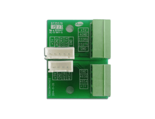
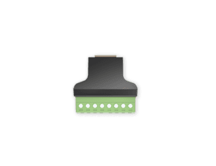
Modern LiFePO4 battery systems often communicate with inverters through CAN, RS485, or related protocols. Closed-loop communication allows the BMS to share state of charge, allowable charge current, allowable discharge current, alarms, temperature status, and protection events. This improves accuracy and reduces reliance on voltage-based estimation.
Where communication is not supported, installers may configure the inverter manually using voltage thresholds. This can work, but it is less precise because LiFePO4 has a relatively flat voltage curve across much of its state-of-charge range. SOC drift, early shutdowns, and inaccurate monitoring are more likely in open-loop systems.
A 48V LiFePO4 battery commonly fits into DC-coupled systems using a hybrid inverter or an off-grid inverter with an MPPT charge controller. DC-coupled designs can be efficient for new systems because PV, battery, and backup loads are integrated through one platform.
In an AC-coupled retrofit system, the 48V battery still connects on the DC side of a dedicated battery inverter or hybrid inverter, which manages charging and discharging control.
Meanwhile, the existing PV generation system typically remains AC-coupled through grid-tied inverters, which operate independently from the battery storage subsystem.
AC-coupled systems may be more practical for retrofits where a facility already has grid-tied PV inverters. In this architecture, a battery inverter manages the storage system on the AC side. EPCs should evaluate grid-interconnection rules, export limitation, backup isolation, control strategy, and whether the battery will be charged only from PV or also from the grid.
For off-grid PV systems, the charge controller must be sized around PV array voltage, maximum current, battery voltage, and battery charge-current limits.
For a typical 48V 200Ah LiFePO4 battery, common charge current references are:
It is important to distinguish between recommended charge current and maximum charge current. The recommended value is used for long-term cycle life optimization, while the maximum value defines the absolute safety limit controlled by the BMS.
Maximum charge current also directly affects PV array and generator sizing. A higher charge limit allows larger PV input or faster generator charging, but it must remain within BMS protection boundaries.
If the PV system or generator supplies current above the battery limit, the BMS may reduce charging current or temporarily disconnect to protect the cells. This can lead to system instability if not properly designed.
For example, if a battery allows a maximum charge current of 100A at 51.2V, the maximum charging power on the battery side is approximately 5.1 kW before conversion losses.
Over-paneling can improve winter and cloudy-day performance, but the controller and battery BMS must be able to manage the available current safely.
A common design mistake is focusing on energy capacity while ignoring maximum charge current. If the PV array and MPPT controller can deliver more current than the battery allows, the system must be configured to limit charging. Otherwise, the BMS may disconnect during high irradiance, causing system instability.
Common mismatch problems include unsupported communication protocols, incorrect charge voltage, excessive discharge current, low-voltage cutoff set too low or too high, and incompatible SOC calibration. These issues may appear as random inverter alarms, reduced runtime, premature shutdown, or repeated BMS protection events.
For B2B projects, it is good practice to validate inverter-battery compatibility before procurement. Installers should request a compatibility list, communication protocol documentation, firmware requirements, and recommended inverter settings for the exact battery model.
LiFePO4 chemistry is relatively stable, but commercial battery storage still requires formal safety review. Compliance depends not only on the battery module but also on the complete energy storage system, including inverter, enclosure, wiring, protection devices, location, and fire safety measures.

Professional buyers should request verifiable certificates tied to the exact model number. Relevant documents may include UN38.3 transport testing, IEC 62619 for industrial lithium battery safety, UL 1973 for stationary battery safety, CE documentation, EMC declarations, RoHS documentation, and regional test reports where applicable.
It is important to distinguish different types of certifications because they serve different purposes in the procurement and approval process.
From a compliance perspective, these documents can be grouped into different layers rather than treated as equivalent requirements. For example, transport certification, product-level safety certification, and system-level approval each address different risks and regulatory needs.
EPCs should avoid treating UN38.3, IEC 62619, and UL 1973 as interchangeable documents, as each one applies to a different stage of the battery lifecycle—from shipping, to product safety validation, to stationary energy storage deployment.
UN38.3 is especially important for logistics because lithium batteries are regulated during transport. IEC 62619 is frequently referenced for industrial lithium cells and batteries. In North American projects, UL 1973 and system-level requirements may be central to permitting and insurance review.
System-level safety standards and fire codes apply when lithium battery storage systems are installed in commercial buildings, dedicated battery rooms, outdoor cabinets, or containerized energy storage systems, based on requirements outlined in the NFPA 855 standard for energy storage system installation and fire safety. Depending on the jurisdiction, requirements may address location, separation distance, ventilation, emergency access, fire detection, signage, and maximum energy capacity per area.
In North American commercial energy storage projects, UL 9540 is often used as the system-level certification standard for complete energy storage systems, including batteries, inverters, and integration components.
In addition, UL 9540A is a testing method used to evaluate thermal runaway fire propagation behavior. It is often required by Authorities Having Jurisdiction (AHJ), fire marshals, or insurance providers to assess fire risk at the system level.
Fire-code thresholds for battery energy storage systems vary significantly depending on jurisdiction, battery chemistry, installation location, building occupancy type, system listing status, and the interpretation of the Authority Having Jurisdiction (AHJ).
As a result, compliance requirements should not be assumed to be uniform across different regions or project types. Even systems using the same battery model may be subject to different approval conditions depending on site classification and regulatory interpretation.
Therefore, EPCs should not assume that a low-voltage modular battery bank is automatically exempt from fire-code review or permitting processes, even when total system voltage is relatively low.
It is important to note that NFPA 855 is an installation standard, not a product certification. It defines how energy storage systems should be installed, including spacing, ventilation, fire suppression considerations, and location requirements, but it does not certify battery products themselves.
In practice, local electrical codes, fire codes, and authority requirements may override manufacturer datasheet claims or generic compliance statements. EPCs should always verify the final approval requirements with the local AHJ before final system design.
For U.S. projects, NFPA 855 is an important reference for stationary energy storage installation requirements. In other regions, local fire authorities, building codes, electrical codes, and insurer requirements may define practical approval conditions. EPCs should confirm requirements early, especially when multiple 48V 200Ah modules create battery banks above 20 kWh, 50 kWh, or other local thresholds.
Grid compliance is usually driven by the inverter and the complete system design. Export control, anti-islanding protection, backup isolation, grid-forming operation, and utility approval all need to be reviewed. A battery added to an existing PV system may change the interconnection arrangement, even if the PV array size remains the same.
For commercial battery storage projects, a structured permitting and AHJ approval workflow is often required before procurement and installation. A typical step-based process includes:
This process helps ensure that the system design aligns with local regulatory and safety expectations before equipment is purchased or installed.
Commercial projects should coordinate battery design with electrical permits, utility requirements, fire authority expectations, and site insurance conditions. This is particularly important for facilities with critical loads, public access, or indoor battery installations.
Lithium batteries used in 48V 200Ah PV storage systems require controlled logistics and compliance with international transport safety regulations, based on the UNECE Manual of Tests and Criteria for lithium battery transport safety (UN38.3 framework). Resellers and EPCs should verify shipping classification, packaging, labeling, documentation, and state-of-charge requirements before moving inventory across borders or to remote project sites. Warehouses should maintain suitable temperature and humidity conditions and avoid long-term storage at very low state of charge.
For channel partners, poor logistics can become a commercial risk. Damaged packaging, missing transport documents, expired stock, or incorrect storage SOC can lead to rejected deliveries, warranty disputes, or failed commissioning.
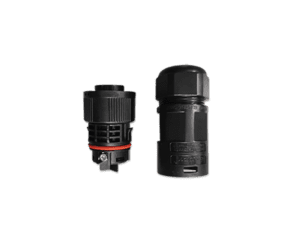
A 48V 200Ah LiFePO4 battery is often marketed as easy to install, but professional deployment still requires careful DC electrical work. Low voltage does not mean low hazard. High current can create severe heating, arcing, and equipment damage if the system is incorrectly wired.
It is important to clarify that low voltage does not mean low hazard. Even at 48V, battery systems can deliver extremely high current levels, which can result in severe heating, arcing, equipment damage, or fire risk if installation is incorrect or protection design is insufficient.
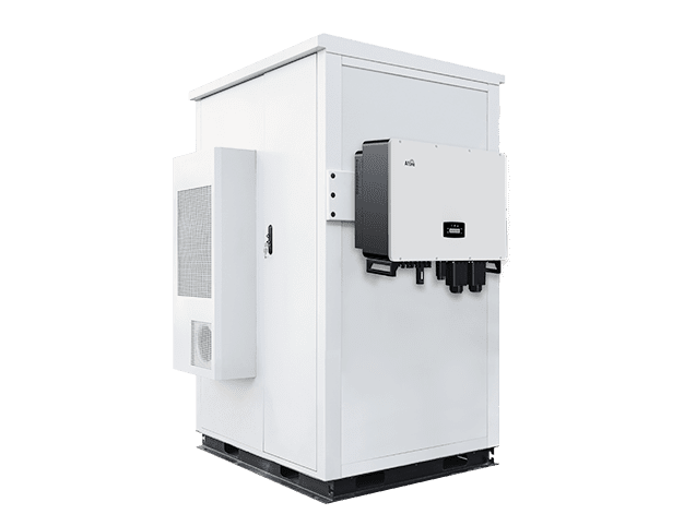
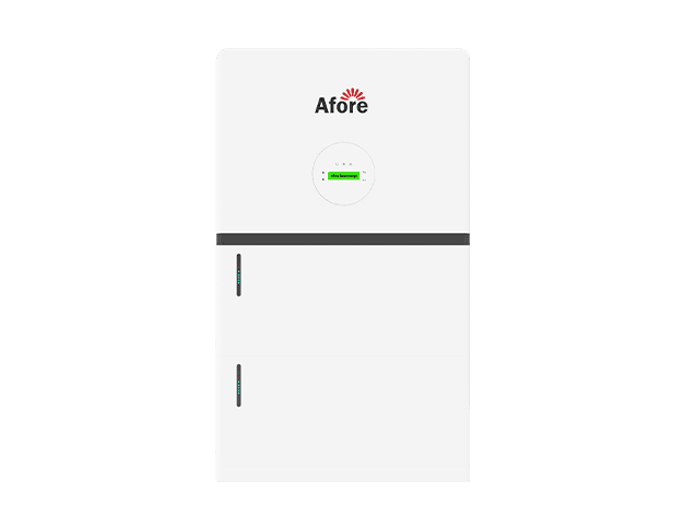
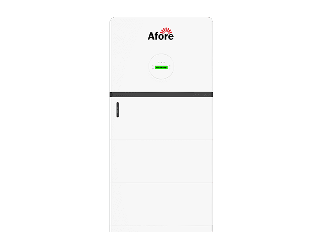
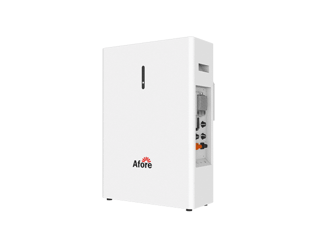
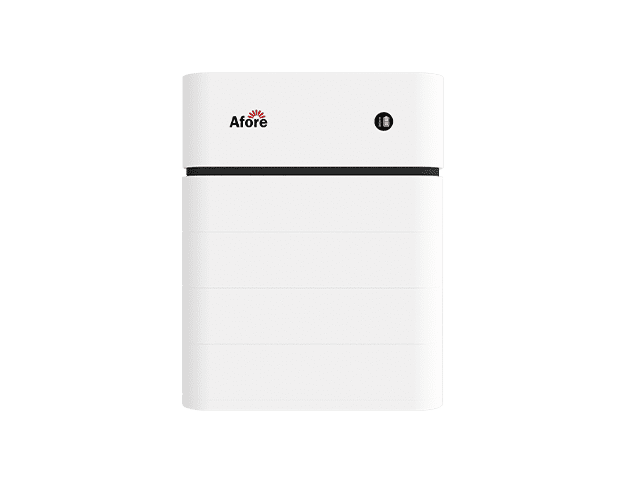
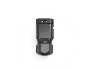
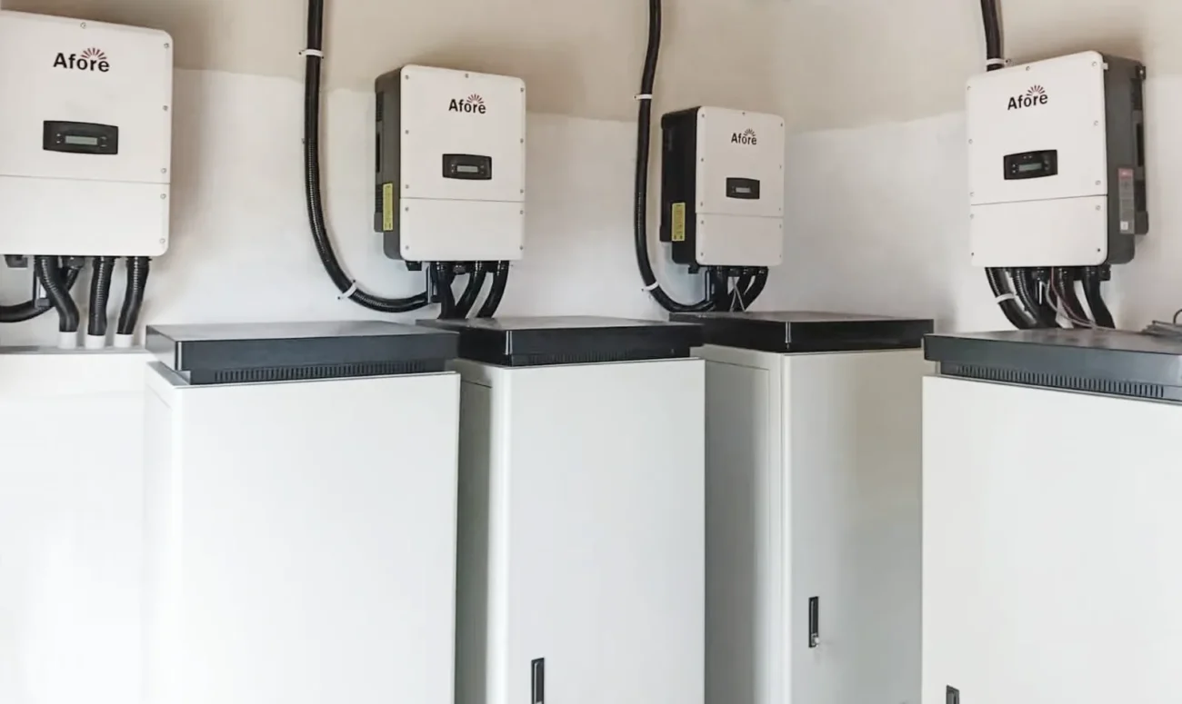
Common form factors include rack-mounted batteries, wall-mounted units, and cabinet-integrated systems. Rack-mounted LiFePO4 battery modules are popular in telecom rooms, equipment shelters, and commercial battery cabinets because they are modular and serviceable.
Typical 48V 200Ah LiFePO4 battery modules used in PV storage systems usually weigh in the range of approximately 40–100 kg per unit depending on enclosure design and energy density. This makes handling and installation planning an important part of system design rather than just electrical engineering.
Rack installations should also be checked for cabinet depth compatibility, as many industrial battery racks require standardized depths to ensure proper mounting, cable routing, and ventilation clearance.
For wall-mounted systems, the structural load capacity of the wall must be verified before installation. Drywall or lightweight partition walls are generally not suitable without reinforcement, especially for heavier lithium battery modules.
Because of the weight of a fully assembled 10 kWh-class module, lifting equipment or at least two-person handling is often required during installation to avoid mechanical damage or personal injury.
Adequate clearance must also be maintained around battery modules for cable bending radius, airflow, and maintenance access. Insufficient clearance can lead to overheating, difficult servicing, or unsafe wiring conditions.
In multi-module cabinet systems, floor loading capacity becomes a critical design factor. When multiple batteries are installed in a single enclosure, the total system weight can exceed several hundred kilograms, requiring proper floor reinforcement and load distribution planning.
Wall-mounted units can save floor space in smaller installations. Cabinet systems may provide cleaner cable routing, environmental protection, and integrated DC distribution.
The right form factor depends on footprint, IP rating, airflow, service clearance, cable entry, seismic or structural requirements, and accessibility for maintenance. Outdoor installations need special attention to heat, moisture, dust, corrosion, and direct sunlight.
DC protection design should account for continuous current, peak current, fault current, cable ampacity, voltage drop, and disconnect requirements. Each parallel battery string may require its own fuse or breaker, depending on system design and local code. Main DC disconnects should be accessible and clearly labeled.
Cable gauge selection is particularly important in 48V systems because current is high relative to power. Long cable runs can create voltage drop that causes inverter faults or unequal current sharing. Installers should use correctly rated lugs, follow torque specifications, protect cables from abrasion, and apply appropriate grounding and bonding practices.
Commissioning should be documented because it affects safety, warranty, and after-sales support. A practical commissioning process normally includes verification of battery voltage, polarity, physical condition, cable torque, breaker ratings, grounding, BMS communication, inverter firmware, charge/discharge limits, SOC calibration, alarm status, and monitoring access.
During commissioning, EPCs should maintain a structured record to ensure traceability and warranty compliance. A standard commissioning checklist should include:
This record ensures that the system baseline is clearly documented before operation begins.
In addition to the documentation checklist, commissioning should always include verification of baseline operating conditions before energizing the system. This includes:
These steps help confirm that both the battery system and inverter are operating within expected design limits before full deployment.
For multi-module systems, addresses and communication wiring should be checked before paralleling. Batteries should be at similar SOC before connection. The installer should perform controlled charge and discharge tests and record operating values under load.
The most common field errors include incorrect inverter charge settings, excessive discharge current, unequal cable lengths in parallel banks, poor ventilation, mixing old and new batteries, leaving batteries at low SOC for extended periods, and installing outdoor cabinets without thermal control.
These mistakes do not always create immediate failure. More often, they reduce usable capacity, increase imbalance, trigger alarms, and shorten service life. For EPCs managing multiple sites, standardized installation procedures can significantly reduce after-sales calls.
LiFePO4 batteries are lower-maintenance than flooded or sealed lead-acid systems, but the overall storage system still requires monitoring and periodic inspection. For commercial portfolios, remote visibility is often the difference between proactive maintenance and expensive emergency service.
The BMS provides valuable operational data, including state of charge, state of health, module voltage, cell voltage balance, battery temperature, charge/discharge current, cycle count, alarms, and communication status. Tracking this data helps identify abnormal behavior before it becomes a failure.
For telecom sites, remote agricultural systems, and distributed commercial facilities, monitoring should be integrated into a broader platform where service teams can compare sites, review alarms, and schedule maintenance efficiently. A battery that quietly loses communication with the inverter may still operate for a time, but dispatch accuracy and protection coordination may suffer.
Preventive maintenance should include visual inspection, terminal torque checks, cabinet cleaning, ventilation checks, firmware review, alarm log review, and verification of inverter settings. Where practical, periodic capacity testing can help confirm whether the battery bank is meeting contractual performance expectations.
Maintenance intervals should reflect site conditions. A clean indoor electrical room may require less frequent physical inspection than a dusty agricultural installation or outdoor telecom shelter. However, even indoor systems should be reviewed regularly because firmware updates, communication errors, and loose connections can affect long-term reliability.
Battery capacity declines over time because of cycle aging, calendar aging, temperature exposure, operating SOC window, and charge/discharge rate. Commercial O&M contracts should define acceptable capacity thresholds and testing methods. Without defined testing procedures, disputes can arise between asset owners, EPCs, and suppliers when runtime appears lower than expected.
A practical approach is to record baseline performance during commissioning and compare it with periodic test results under similar conditions. This gives both the installer and owner a more objective view of degradation.
A high-quality 48V 200Ah LiFePO4 battery can last for thousands of cycles, but service life depends on operating conditions. Shallow cycling, moderate temperatures, correct charge settings, conservative C-rates, and good BMS protection support longer life. High heat, frequent deep discharge, high current, poor ventilation, and incorrect inverter settings reduce life.
For financial modeling, EPCs should use conservative assumptions aligned with documented warranty conditions rather than the most optimistic datasheet cycle claim. This is especially important for projects where the battery cycles daily or supports revenue-generating services.
For B2B buyers, procurement risk often appears after the purchase order is issued. A low-cost battery may look attractive until the project team discovers missing certifications, limited inverter support, unclear warranty terms, or poor replacement procedures.
Professional buyers should evaluate cell sourcing, cell matching, BMS capability, balancing strategy, production testing, enclosure quality, and quality-control processes. Consistency is particularly important when multiple batteries are installed across several commercial sites. Small variations in internal resistance, firmware, or BMS behavior can complicate commissioning and service.
A strong BMS should provide reliable protection, accurate SOC estimation, clear alarms, and stable communication with common inverter platforms. Passive or active balancing strategy should be appropriate for the module design and expected operating profile.
Before approving a battery for a commercial PV project, EPCs and resellers should request a complete documentation package. The minimum set normally includes the datasheet, installation manual, warranty terms, certification reports, safety data sheet, transport documentation, inverter compatibility list, communication protocol guide, and after-sales service procedure.
These documents are not administrative extras. They support permitting, logistics, installer training, commissioning, warranty claims, and future maintenance. Missing documentation can delay projects even when the hardware itself is available.
Warranty length alone is not enough. Buyers should examine exclusions, required operating limits, claim procedures, labor coverage, replacement timelines, and whether local service is available. A 10-year warranty with slow response and unclear responsibility may be less valuable than a shorter warranty with strong technical support and local stock.
Warranty terms should be evaluated as a structured set of conditions rather than a single duration figure. EPCs should carefully review the following warranty clauses:
For EPCs responsible for performance guarantees, supplier responsiveness is a major risk factor. Firmware support, BMS troubleshooting, replacement module availability, and compatibility updates can affect the profitability of service contracts.
Resellers should manage battery inventory carefully. Long storage periods, unsuitable warehouse temperatures, low SOC, damaged packaging, and changing certification requirements can erode margins. Compatibility-related returns are another common risk when batteries are sold without clear inverter guidance.
For global channels, regional compliance matters. A model suitable for one market may lack the documentation needed for another. Resellers serving EPCs should avoid stocking batteries that cannot be supported with verifiable certificates, manuals, and integration data.
A 48V 200Ah LiFePO4 battery is usually more expensive upfront than an equivalent lead-acid bank, but purchase price is a poor measure of value. Commercial PV economics should be evaluated on usable lifetime energy, reliability, maintenance cost, replacement intervals, and operational benefits.
Lead-acid batteries may have lower initial cost, but they usually offer lower usable depth of discharge, shorter cycle life, lower round-trip efficiency, and more maintenance. LiFePO4 batteries typically provide higher usable capacity from the same nominal rating and can reduce space and weight requirements.
For daily cycling PV applications, LiFePO4 often has a lower lifetime cost per delivered kWh, even if initial CAPEX is higher. This advantage becomes stronger where maintenance access is expensive or where downtime has commercial consequences.
Reduced maintenance is a major value driver. Lead-acid systems may require regular inspection, watering in flooded designs, equalization, ventilation considerations, and more frequent replacement. LiFePO4 systems reduce many of these tasks, although electrical inspections and monitoring remain necessary.
For remote telecom sites, farms, islands, mining support facilities, and distributed commercial portfolios, fewer truck rolls can materially improve total cost of ownership. The avoided cost of emergency service may be as important as the battery price itself.
The economic case for a 48V solar battery bank depends on the site’s tariff and operational objective. Key drivers include time-of-use pricing, demand charges, outage costs, diesel generator offset, self-consumption improvement, incentives, and battery dispatch strategy.
A single 10 kWh-class battery may not deliver meaningful demand-charge reduction for a large facility, but it may be valuable for critical-load backup. Conversely, a bank of multiple modules may improve self-consumption in a small commercial site with afternoon PV surplus and evening demand. The use case must be defined before ROI is calculated.
A practical comparison between battery models should include usable capacity, round-trip efficiency, degradation, warranty throughput, installation cost, O&M cost, and replacement cost. EPCs can use this framework to compare competing 48V lithium battery options more objectively than by nominal kWh price alone.
For example, a lower-priced battery with limited cycle warranty, weak documentation, and poor inverter compatibility may create higher lifecycle cost than a more expensive module with better support and longer usable life.
The modular nature of 48V 200Ah batteries is one of their strongest advantages. EPCs can standardize around repeatable building blocks and scale capacity by adding modules. However, modularity has limits.
Multiple 48V 200Ah batteries can be combined to build 20 kWh, 40 kWh, 60 kWh, or larger banks where supported by the manufacturer and inverter. As systems grow, DC current, busbar capacity, protection coordination, cabinet layout, and heat management become more important.
A standardized battery cabinet with defined cable lengths, breaker ratings, communication layout, and commissioning steps can reduce engineering time. This is especially useful for EPCs deploying similar systems across retail chains, telecom sites, agricultural facilities, or remote monitoring portfolios.
Using a limited set of approved battery models can reduce training requirements, spare-parts complexity, and commissioning errors. It also helps procurement teams negotiate better terms and helps O&M teams build familiarity with alarm behavior, firmware, and replacement procedures.
Standardization should not mean ignoring site-specific requirements. Climate, load profile, fire code, grid rules, and expansion plans still need individual review. However, a controlled product list improves quality management across repeated deployments.
A move to high-voltage ESS becomes more attractive when projects require higher inverter power, larger three-phase integration, demand-charge management, centralized energy storage, or hundreds of kWh of capacity. High-voltage systems reduce DC current and can improve efficiency at scale.
The transition also changes the safety and compliance profile. High-voltage systems require different technician training, PPE procedures, enclosure design, and permitting review. The right decision is not simply “48V versus high-voltage,” but which architecture best fits power level, service capability, expansion plans, and regulatory requirements.
Key project triggers for transitioning to high-voltage ESS include:
When these conditions are present, high-voltage systems typically offer better efficiency, lower cable losses, and simpler system scaling.
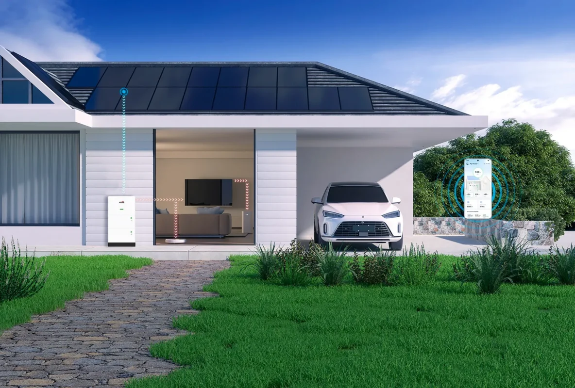
Commercial energy systems are becoming more integrated. Batteries increasingly need to coordinate with PV, grid import limits, EV charging, generators, building loads, and energy management systems. Before selecting a 48V battery platform, EPCs should consider whether the BMS and inverter can support remote monitoring, open communication, firmware updates, export control, and future expansion.
A battery system that works for today’s backup requirement may become limiting if the client later adds EV chargers, expands PV, or participates in dynamic tariff programs. Future-proofing should be discussed during the design stage, not after installation.
A 48v 200ah lifepo4 battery is best treated as a modular 10 kWh-class storage component within a complete PV energy system. For professional projects, the deciding factors are not only nominal capacity and price, but inverter compatibility, BMS communication, usable power, thermal environment, safety documentation, commissioning quality, O&M visibility, and lifecycle cost.
For EPCs, installers, and commercial buyers, the safest approach is to size from the load profile, verify compatibility before purchase, document all inverter and BMS settings, and evaluate suppliers on supportability as much as product specifications. When applied within its proper power and capacity range, a 48V 200Ah LiFePO4 battery can provide reliable, scalable storage for distributed PV systems and critical commercial loads.
A 48V 200Ah LiFePO4 battery provides about 9.6 kWh nominal energy, or around 10.24 kWh in 51.2V systems. Usable energy depends on depth of discharge and inverter efficiency. In real PV applications, delivered AC energy is typically lower than the nominal rating. Final usable capacity varies by system configuration and operating limits.
Yes, but only for small critical loads. Runtime depends on usable energy and inverter efficiency, not just nominal capacity. A single module may support light commercial loads for a limited duration. Larger applications usually require multiple batteries in parallel.
No, compatibility depends on electrical and communication matching. The inverter must support the battery’s voltage range and charging limits. Communication protocols like CAN or RS485 may be required for proper control. Manufacturer-approved inverter lists should always be checked.
Yes, but only within the manufacturer’s specified limits. All batteries must be at similar SOC before connection.
Correct cabling, protection devices, and communication setup are required. Mixing mismatched or aged batteries can reduce system performance.
Typical cycle life ranges from 3,000 to 6,000 cycles under standard conditions. The real-world lifespan is usually around 8–15 years for daily cycling systems. Performance depends on temperature, discharge depth, and operating current. Proper installation and thermal management help extend service life
https://unece.org/transport/dangerous-goods/un-manual-tests-and-criteria
https://www.nfpa.org/codes-and-standards/nfpa-855-standard-development/855