


A solar charge controller inverter can simplify the way PV generation, battery charging, and AC power supply work together, but it can also introduce system-level risk if it is specified like a consumer device rather than a commercial energy asset. For EPCs, installers, system integrators, resellers, and facility owners, the key consideration is not rated power alone, but whether the system architecture aligns with the site requirements, including load profile, battery strategy, grid connection conditions, service model, and future expansion needs.
In commercial and industrial PV projects, the wrong inverter-charger architecture can reduce PV yield, shorten battery life, complicate utility approval, increase commissioning time, and create recurring service issues. This is especially true for off-grid sites, weak-grid facilities, telecom power systems, agricultural operations, islanded microgrids, backup power installations, and solar-plus-storage projects where PV, batteries, loads, generators, and the grid may all interact.
This guide explains what a solar charge controller inverter is, how it differs from standard inverters, when it makes sense in commercial PV systems, and how to evaluate sizing, battery compatibility, grid compliance, installation quality, monitoring, supplier capability, and lifecycle economics.
This guide focuses on integrated inverter-charger systems with built-in MPPT solar charging. In some cases, separate MPPT controllers or AC-coupled systems may be more appropriate depending on scalability and redundancy requirements.
A solar charge controller inverter is either an integrated device or a tightly coordinated system that manages PV input, battery charging, and AC output. In many commercial contexts, the term is used interchangeably with hybrid сонячний інвертор, inverter charger for solar system, all-in-one inverter charger, or off-grid solar inverter. However, these terms do not always describe the same internal architecture, and that matters during procurement.
A charge controller regulates DC power from PV modules into a battery bank. A solar inverter converts DC power into AC power for loads or grid export. A hybrid inverter usually manages solar, battery, grid, and load-side power flows. An inverter charger can convert battery DC into AC for loads and also use AC input from the grid or a generator to charge batteries. An all-in-one solar charge controller inverter often combines MPPT solar charge control, DC-to-AC inversion, and AC battery charging in one enclosure.
For conventional grid-tied commercial PV systems without batteries, string or central inverters are usually the standard choice. These inverters typically include integrated MPPT for PV harvesting, but they are not necessarily designed to charge batteries directly. By contrast, off-grid and hybrid systems need controlled battery charge and discharge functions, backup load management, and sometimes grid-forming capability. This is where a solar charge controller inverter becomes relevant.
| Device Type | Фотоелектричний вхід | Зарядка акумулятора | AC Output | Взаємодія з мережею | Найкращий варіант використання |
|---|---|---|---|---|---|
| Solar charge controller inverter | Yes (integrated MPPT) | Yes (built-in) | Так. | Limited / depends on model | Off-grid / hybrid systems |
| Grid-tied inverter | Так. | Ні. | Так. | Yes (grid-following only) | Utility-scale PV export |
| Inverter charger | Yes (optional) | Так. | Так. | Yes / generator support | Backup + off-grid systems |
| Гібридний інвертор | Так. | Так. | Так. | Yes (grid + storage) | Solar + storage + backup |
| All-in-one inverter charger | Так. | Так. | Так. | Так. | Compact C&I hybrid systems |
MPPT does not automatically mean battery charging capability.
MPPT functions are used differently depending on inverter architecture:
The main difference between these systems is how energy storage and power flow are managed. A standard grid-tied inverter converts DC power from solar panels into AC power synchronized with the grid and typically shuts down during a grid outage unless backup functionality is integrated. A solar charge controller inverter is designed around energy storage and can coordinate PV input, battery charging and discharging, and AC load supply within a single integrated system.
This distinction is important in commercial PV design because MPPT capability alone does not indicate battery compatibility or hybrid system functionality.
In hybrid and off-grid systems, the inverter charger may operate in multiple modes, including supplying AC loads, charging batteries from PV or generator input, drawing power from the grid, and switching between operating priorities based on system settings and load demand.
For this reason, EPCs should avoid relying on product naming alone. Datasheets should be reviewed to confirm whether the equipment is grid-tied, off-grid, hybrid, grid-forming, grid-following, battery-ready, export-capable, or backup-only.
In a professional PV project, the core functions of a solar charge controller inverter are closely linked. The MPPT solar charge controller harvests PV energy within a defined voltage and current window. The battery charger applies the correct charging profile for the selected chemistry. The inverter supplies AC power to loads at the required voltage, frequency, waveform quality, and phase configuration. If the system interacts with the grid, it must meet interconnection rules, anti-islanding requirements, export limits, and power quality standards.
MPPT and PWM are two common solar charge control methods used in PV systems. MPPT (Maximum Power Point Tracking) is widely used in commercial solar charge controller inverter systems because it can continuously optimize voltage and current to harvest more energy under changing irradiance and temperature conditions. PWM (Pulse Width Modulation) is more commonly used in small or low-cost solar systems and is generally less suitable for commercial PV applications due to lower energy harvesting efficiency.
The selection between MPPT and PWM depends on several factors, including PV array voltage relative to battery voltage, temperature variation at the installation site, partial shading conditions, system cost constraints, and required energy yield efficiency. In most commercial PV projects, MPPT is preferred because it improves overall system performance and long-term energy output.
Several specifications should be reviewed together, not separately. PV input voltage must match the module string design under both cold and hot conditions. The MPPT operating range must suit the actual string voltage during normal operation. Battery voltage must match the inverter charger’s supported DC bus. Charge and discharge current limits must be compatible with the battery bank and BMS. The AC output rating must match both continuous load demand and short-duration surge requirements.
The practical impact is significant. If the PV string voltage operates outside the MPPT window, production falls. If battery charging parameters are incorrect, battery life declines. If surge capacity is insufficient, pumps, compressors, refrigeration systems, or tools may trip the inverter. If grid parameters are unsupported, the project may fail inspection or utility approval.
A solar charge controller inverter is most valuable where PV generation, battery storage, and controlled AC output must operate as one coordinated system. Typical commercial applications include telecom base stations, agricultural pumping and cold storage, remote warehouses, rural clinics, construction sites, island facilities, mining support buildings, border stations, small industrial loads, and commercial sites with unreliable grid supply.
In these projects, the business case is often based on uptime, generator fuel reduction, energy resilience, or reduced grid dependence. For example, a telecom site may prioritize low truck-roll frequency and autonomous operation. An agricultural facility may value PV-powered daytime loads with battery support for evening controls or refrigeration. A weak-grid commercial building may need self-consumption during normal operation and backup power during outages.
This differs from a large grid-export solar farm, where standard string or central inverters may be more appropriate. In export-oriented projects, battery charge control may be handled by separate battery inverters or utility-scale power conversion systems rather than an integrated inverter charger.
A solar charge controller inverter may not be the best choice in the following cases:
Many hybrid solar inverters include integrated MPPT charge control, so a separate charge controller is not always required. However, external MPPT solar charge controllers are still used in some commercial systems for higher PV capacity, modular expansion, redundancy, or specific battery-bank design requirements.
For instance, an off-grid facility may use an all-in-one inverter charger for core AC supply while adding external MPPT controllers to expand PV capacity without replacing the inverter. A remote microgrid may split PV charging across multiple controllers so that one failed controller does not remove all solar production. In other cases, battery voltage, PV string length, or array orientation may make external controllers more practical.
The correct answer depends on the actual product architecture and system design. EPCs should confirm the number of MPPT inputs, maximum PV input voltage, input current limits, charging current capacity, and whether the inverter can accept additional external charging sources.
Architecture should be defined early because it affects electrical design, protection, and system performance.
Different inverter charger configurations may support different operating modes, so selection must follow system requirements rather than product assumptions.
In a DC-coupled system, PV power is connected on the DC side and can charge the battery before being inverted to AC. This is common with all-in-one inverter chargers and hybrid inverters. DC coupling can be efficient for storing solar energy because PV energy may be converted fewer times before entering the battery. It can also simplify small-to-medium off-grid and hybrid systems because PV, battery, and inverter functions are coordinated inside one platform.
In an AC-coupled system, PV inverters feed an AC bus, while a battery inverter charges and discharges storage through the AC side. This can be attractive for retrofits, especially where an existing grid-tied PV system is already installed. AC coupling can offer flexibility and scalability, but it may require more complex control logic to prevent overproduction, manage frequency shifting, coordinate backup islanding, and comply with export limits.
| Архітектура | Best fit | Key advantage | Main design risk |
|---|---|---|---|
| DC-coupled solar charge controller inverter | New off-grid, hybrid, backup, weak-grid projects | Integrated PV-battery-load control | PV input and battery limits must be carefully matched |
| AC-coupled solar-plus-storage system | Existing PV retrofits, larger commercial systems | Flexible expansion with existing inverters | Control coordination and grid compliance can be more complex |
| Separate charge controller and inverter | Modular off-grid or high-redundancy systems | Greater design flexibility | More components and more commissioning work |
Hybrid inverter charger systems are often used for commercial backup, solar self-consumption, peak shaving, and generator integration. In normal operation, PV may supply loads first, charge batteries second, and export or curtail excess energy depending on the permitted operating mode. During a grid outage, the inverter may isolate critical loads and operate as a grid-forming source if it is designed and approved for backup islanding.
Backup design should be based on load classification rather than total building load. A commercial facility may have hundreds of kilowatts of connected load, but only a smaller set of critical loads may need backup power. These may include IT systems, lighting, security, refrigeration controls, communications, access control, water pumps, or selected production equipment.
Transfer time is also important. Some systems behave like a UPS with very fast transfer, while others have a longer transition that may not be suitable for sensitive equipment. Generator start/stop logic, battery reserve settings, and critical load panel design should be defined before selecting equipment.
Off-grid systems require more conservative design because there is no grid to absorb mistakes. The inverter and charge controller must maintain power through daily load variation, seasonal irradiance changes, cloudy periods, battery aging, and possible generator constraints.
Battery autonomy is a central design parameter. A remote communications site may require one to three days of autonomy, while a remote commercial facility with generator backup may accept shorter autonomy if fuel logistics are manageable. PV oversizing is often necessary to recharge batteries during low-irradiance seasons, but excessive oversizing can create curtailment and thermal stress if the system cannot use or store the energy.
Load-shedding strategies are also important. Instead of allowing a full shutdown when battery state of charge falls, the system can disconnect non-critical loads first. For remote assets, this can protect essential operations and reduce emergency service visits.
Not all solar charge controller inverter products are approved for grid export. Some are designed only for off-grid operation or backup-only use. Others can interact with the grid but may require specific firmware, certified settings, external meters, or utility-approved export control functions.
Commercial projects should confirm whether the equipment is grid-forming, grid-following, or capable of both modes. Grid-following inverters synchronize with an existing grid and disconnect when grid conditions fall outside limits. Grid-forming inverters can establish voltage and frequency for islanded loads. Some hybrid systems switch between these roles depending on whether the grid is present.
Grid-interactive projects must consider anti-islanding, export control, voltage and frequency ride-through, power factor control, and local interconnection documentation. IEEE 1547 is a widely referenced standard for distributed energy resource interconnection in the United States, while other regions apply their own grid codes and technical requirements.
Sizing is not a single wattage calculation. It is a system process that begins with the load profile and ends with coordinated ratings for PV input, battery storage, inverter output, protection devices, and expansion capacity.
PV string design must consider voltage behavior under both low-temperature and high-temperature conditions. At low temperatures, module open-circuit voltage increases, which means the maximum PV input voltage of the inverter must not be exceeded under the coldest site conditions. At high temperatures, operating voltage decreases, which means the PV string must still remain inside the MPPT operating window to ensure stable energy harvesting.
Many inverter charger systems allow PV array oversizing as long as voltage and current limits are not exceeded. This is often expressed through a DC/AC ratio, where the PV array capacity is higher than the inverter AC rating to improve energy production over time.
PV oversizing provides several advantages, including better low-light performance, faster battery recharge after discharge cycles, and improved annual energy yield. However, it also introduces trade-offs such as peak power clipping at high irradiance, higher thermal loading on the inverter, potential curtailment when batteries are full, and operation limits defined in the manufacturer datasheet or warranty conditions.
For commercial EPC design, it is essential to verify the following parameters together rather than individually: maximum recommended PV array power, maximum PV open-circuit voltage, maximum input short-circuit current, MPPT current limit per tracker, battery charge current limit, and inverter derating behavior when PV production exceeds load or battery acceptance capacity.
In commercial systems with multiple roof orientations or shading conditions, multiple MPPT trackers can improve yield by separating differently oriented PV strings. However, MPPT configuration must still respect total current limits and voltage boundaries of the system.
Commercial loads are rarely as simple as their nameplate wattage. Pumps, HVAC compressors, refrigeration systems, motors, power tools, elevators, and certain industrial machines can draw high inrush current at startup. An inverter that appears adequate based on continuous kW may trip if it lacks surge capacity or kVA headroom.
EPCs should review both kW and kVA ratings. Power factor matters because some commercial loads require apparent power that exceeds real power. Three-phase loads require careful phase configuration, especially where parallel inverter units are used to build a three-phase system.
| Sizing item | Why it matters in commercial PV |
|---|---|
| Continuous AC output | Determines normal load-serving capability |
| Surge or overload rating | Supports motor starts and transient loads |
| kW and kVA rating | Accounts for power factor and apparent power |
| Phase configuration | Must match single-phase, split-phase, or three-phase loads |
| Transfer time | Determines suitability for critical backup loads |
| Output waveform and THD | Affects sensitive electronics and motor performance |
Commercial solar charge controller inverter systems often operate in three-phase configurations for medium and large-scale loads. There are two main approaches: native three-phase inverter chargers and systems built by paralleling multiple single-phase units.
Native three-phase inverter chargers provide tightly synchronized phase output and are generally simpler to manage. Paralleled single-phase systems can achieve similar power capacity but require careful synchronization and communication between units.
Three-phase design must account for phase imbalance limits, neutral current loading, and motor-start behavior under uneven phase demand. In commercial environments, unbalanced loads are common and can affect system stability if not properly managed.
Redundancy behavior is also important. In some systems, if one inverter unit in a three-phase cluster fails, the entire system may shut down. In more advanced architectures, remaining units may continue operating at reduced capacity, depending on design and manufacturer logic.
For motor-driven loads, starting current can create temporary imbalance across phases, which must be considered during inverter selection and system design.
Low-frequency inverter chargers typically use transformer-based designs and are known for strong surge handling and excellent motor-start capability. However, they are generally heavier, larger, and may have lower efficiency compared to high-frequency models.
High-frequency inverter chargers are more compact and lightweight, making them suitable for space-constrained commercial installations. However, they may have stricter surge limitations and require more precise load matching.
The selection between high-frequency and low-frequency designs should be based on load characteristics rather than rated power alone. Motor-heavy applications such as pumps, compressors, and industrial equipment often benefit from low-frequency designs, while lightweight commercial loads and space-limited installations may favor high-frequency systems.
A practical approach is to separate loads into critical, deferrable, and non-critical categories. The inverter should be sized for the critical load panel and realistic coincident demand, not simply the total site connection capacity.
Battery sizing should be based on usable energy, not nominal capacity. Usable energy depends on depth-of-discharge limits, temperature derating, inverter losses, battery age, and required reserve. A battery bank rated at 100 kWh may provide less usable energy if the design limits discharge to preserve cycle life or maintain backup reserve.
C-rate is equally important. A battery may have enough energy capacity but insufficient discharge current to support peak inverter output. Lithium batteries typically require communication between the BMS and inverter charger so that charge and discharge limits can be adjusted based on temperature, state of charge, cell balancing, and fault status. Lead-acid systems rely more heavily on voltage-based charge stages and require more attention to ventilation, maintenance, and depth of discharge.
Battery voltage also affects current. Lower-voltage systems require higher current for the same power, increasing cable size, voltage drop, and thermal stress. Commercial systems commonly favor higher DC bus voltages where supported because they reduce current and improve practical wiring design.
Commercial system sizing should be based on measurable load and energy requirements rather than nameplate assumptions. The following formulas are commonly used in preliminary design:
Daily energy demand = Load power × operating hours
Required battery capacity = Daily energy demand × autonomy days ÷ allowable DoD ÷ inverter efficiency
Inverter rating ≥ maximum coincident critical load
Surge rating ≥ highest motor-start or transient load
PV array size = Daily energy demand ÷ peak sun hours ÷ system efficiency
Worked example: A remote commercial facility has a critical load of 12 kWh/day, requires 2 days of autonomy, uses 80% allowable depth of discharge, and has 92% inverter efficiency.
Required battery capacity = 12 × 2 ÷ 0.8 ÷ 0.92 ≈ 32.6 kWh nominal battery capacity.
A solar charge controller inverter should be sized according to critical load demand, PV array capacity, battery voltage, required autonomy, grid availability, operating mode, and future expansion. Measured load data is better than utility bill averages because utility bills show total energy consumption but often hide demand spikes, motor-start events, and time-of-day load behavior.
For example, a remote agricultural site may have a 20 kW average daytime load but a 45 kVA motor-start requirement. A backup-focused office building may have a low critical load most of the day but require fast transfer for IT and security systems. A telecom site may have a modest continuous load but strict uptime requirements and limited access during extreme weather.
The safest commercial sizing process is to begin with load measurement, define backup duration, select the battery bank, design PV around seasonal production, and then select an inverter charger that can handle normal operation, fault conditions, and expansion.
Battery integration is one of the most important differences between a simple solar inverter and a solar charge controller inverter. The battery is not just an energy container; it directly affects power availability, safety, lifecycle cost, and control strategy.
Commercial projects increasingly use lithium iron phosphate, commonly referred to as LiFePO₄, because of its safety profile, cycle life, high usable depth of discharge, and lower maintenance compared with lead-acid systems. However, compatibility must be verified at the inverter charger level. A lithium battery may require specific voltage windows, current limits, wake-up behavior, communication protocols, and firmware support.
Lead-acid batteries remain relevant in some cost-sensitive or legacy off-grid applications, but they require more conservative depth of discharge, proper temperature compensation, ventilation, and periodic maintenance. Flooded lead-acid systems introduce additional site safety and maintenance considerations, while sealed lead-acid systems reduce maintenance but still have cycle-life and temperature limitations.
The key point for EPCs is that battery chemistry affects more than the battery cabinet. It affects charger settings, enclosure design, ventilation, fire risk assessment, lifecycle cost, and warranty compliance.
For lithium systems, BMS communication is often essential. The battery management system reports state of charge, state of health, temperature, allowable charge current, allowable discharge current, alarms, and fault conditions. Communication may occur through CAN, RS485, Modbus, or proprietary protocols.
Closed-loop communication allows the inverter charger to adjust operation based on real battery conditions. Without it, the system may rely on voltage-based control, which is less precise for lithium batteries because their voltage curve can remain relatively flat across much of the state-of-charge range. This can lead to inaccurate SOC estimation, unexpected shutdowns, or conservative operation that reduces usable capacity.
Battery compatibility should be verified at system level including chemistry, communication protocol, and firmware matching.
The operating strategy should be defined before equipment selection. A solar battery storage system designed for backup may preserve a high minimum state of charge and cycle infrequently. A system designed for peak shaving may cycle daily to reduce demand charges. A self-consumption system may prioritize using PV onsite rather than exporting it. A generator-hybrid system may use batteries to reduce generator runtime and avoid inefficient low-load operation.
These strategies produce different battery cycling patterns and financial outcomes. Peak shaving can improve economics in markets with high demand charges, but it increases battery cycling. Backup reserve improves resilience but may reduce daily usable capacity. Time-of-use optimization depends heavily on tariff structure and control accuracy.
Commercial users should define the primary value driver clearly: energy savings, demand reduction, resilience, fuel savings, carbon reduction, or a combination of these. The control mode should support that business objective.
Improper charge settings, high operating temperature, excessive cycling, and poor ventilation can shorten battery life. Lithium batteries may reduce charge or discharge current at low or high temperatures, while lead-acid batteries may suffer accelerated degradation in heat and reduced capacity in cold conditions.
Battery enclosures should be designed for the local environment. Indoor installations may require fire separation, ventilation, and emergency access. Outdoor installations require appropriate ingress protection, thermal management, corrosion resistance, and cable protection. Remote monitoring should include battery alarms, temperature trends, SOC behavior, and communication faults.
Battery replacement timing can dominate lifecycle cost. A lower-cost system that causes premature battery degradation may become more expensive than a better-integrated system with stable operation and stronger monitoring.
Compliance requirements vary by country, utility, system size, and operating mode. Off-grid systems, backup-only systems, export-limited systems, and grid-export systems may face different approval pathways. EPCs should treat certification as a core specification, not an afterthought.
Certification requirements for a solar charge controller inverter depend on system type, operating mode, and regional regulations. Different markets require different combinations of safety, grid interconnection, EMC, and battery-related compliance.
Compliance matrix for commercial PV inverter systems
| Region / Category | Key Requirements |
| Сполучені Штати | UL 1741, IEEE 1547, NEC Articles 690 / 705 / 706 |
| Європа | EN 50549, CE marking, local grid code requirements |
| International Safety | IEC 62109 (inverter safety) |
| PV Grid Interface | IEC 61727 |
| EMC Requirements | IEC 61000 series |
| Battery Energy Storage | Local fire code, battery safety standards, installation regulations |
IEC 62109 is widely used internationally for inverter safety requirements in photovoltaic power conversion systems.
Procurement teams should request certificates, type test reports, and declarations of conformity. It is also important to confirm that the exact model and firmware version are included in the certification scope.
Final compliance requirements always depend on jurisdiction, utility rules, system size, and whether the system operates in grid-tied, hybrid, or off-grid mode.
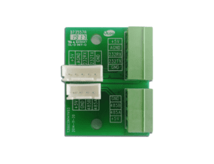
A solar charge controller inverter brings together PV input, battery circuits, AC output, and sometimes grid or generator input. Protection must be coordinated across all of these interfaces.
DC disconnects, string fuses, battery fuses or breakers, AC breakers, surge protection devices, grounding, residual current protection, and isolation monitoring may all be required depending on system design and local code. Battery circuits can carry very high currents, so cable sizing, lug quality, torque settings, insulation rating, and overcurrent protection are critical.
Commercial installers should follow manufacturer wiring diagrams and local electrical regulations. They should also document protection settings, cable routes, breaker ratings, grounding method, and labeling for future O&M.
Grid-interactive systems must disconnect safely during grid outages unless they are designed and approved to supply an intentional island, such as a backup load panel or microgrid. Anti-islanding protection prevents the inverter from energizing a utility line when workers may expect it to be de-energized.
Export control is increasingly important for facilities with limited export permits or weak distribution networks. Zero-export systems typically require external meters or current transformers to measure grid flow and dynamically limit inverter output. Incorrect CT orientation, communication failures, or unsupported meter protocols can cause failed commissioning or utility non-compliance.
European markets often reference network codes and national implementation rules for generator and distributed energy resource connection requirements.
Battery-based solar charge controller inverter systems require structured battery safety design because lithium energy storage systems carry thermal and electrical risks if improperly installed, configured, or maintained. Fire safety compliance should be treated as a mandatory engineering requirement in commercial PV and storage projects.
Battery safety compliance typically includes multiple layers of certification and verification. These may include battery cabinet certification, cell-level, module-level, and rack-level certifications depending on system architecture. Fire test documentation may also be required in certain jurisdictions to demonstrate thermal stability and propagation resistance under fault conditions.
Emergency planning is a critical part of battery system design. Commercial installations should include documented emergency response plans, clear signage, restricted access zones, and defined clearance distances around battery enclosures. These measures ensure safe maintenance access and reduce operational risk during fault conditions.
All installations should also be reviewed by the local Authority Having Jurisdiction (AHJ), which may include fire departments, electrical inspectors, or building safety regulators. AHJ review often determines final approval for system commissioning and energization.
Installation design must also consider physical separation between battery systems, occupied buildings, and critical infrastructure. Fire-rated enclosures, ventilation systems, controlled access areas, and defined exclusion zones are commonly required depending on system size and location.
Fire detection and suppression expectations vary by project scale. Typical requirements may include smoke detection, thermal sensors, alarm integration, and in some cases specialized suppression systems designed for electrical or lithium battery fires.
Emergency shutdown design is also required. EPCs should ensure clearly labeled AC and DC disconnects, shutdown procedures, and clearly documented isolation points accessible to maintenance personnel and first responders.
Thermal runaway risk assessment should evaluate charging behavior, ambient temperature conditions, ventilation efficiency, and worst-case cascading failure scenarios across battery modules.
Indoor and outdoor installations have different compliance requirements. Outdoor systems must address environmental exposure such as water ingress, dust, corrosion, and temperature cycling. Indoor systems require stricter fire compartmentalization, ventilation control, and emergency response coordination.
For commercial projects, fire safety must be treated as a system-level engineering discipline rather than a final installation checklist item.
Hybrid and storage-integrated systems fail more often from design and commissioning errors than from headline equipment limitations. Because the system combines PV, batteries, AC loads, grid input, generator input, monitoring, and protection, installation quality has a direct impact on reliability.
Environmental conditions affect inverter derating, cooling, service life, and enclosure selection. High ambient temperatures can reduce output capacity or accelerate component aging. High altitude may require derating because reduced air density lowers cooling effectiveness. Dust and agricultural contaminants can clog fans and filters. Coastal environments require corrosion-resistant hardware and enclosures.
The equipment’s IP or NEMA rating should match the installation environment. However, enclosure rating alone is not enough. Installers should also check operating temperature range, derating curves, ventilation clearances, mounting orientation, and service access.
Battery cables deserve special attention because current levels can be high. Long cable runs, undersized conductors, poor crimps, loose terminals, or incorrect torque can cause voltage drop, overheating, nuisance trips, and reduced inverter performance.
PV input cables must be sized for current, voltage, installation method, and environmental exposure. AC output wiring must match load current, breaker coordination, grounding method, and phase configuration. Communication cables for BMS, meters, and monitoring should be routed and protected to reduce interference and mechanical damage.
In commercial systems, neat wiring is not only an aesthetic issue. It improves troubleshooting, reduces installation risk, and supports future expansion.
Commissioning should be documented in detail because future warranty claims and service work often depend on knowing the original settings. A concise commercial commissioning checklist should include the following steps.
| Commissioning area | Key checks |
|---|---|
| Pre-energization | Polarity, torque, insulation resistance, grounding, disconnect operation |
| PV input | String voltage, MPPT range, current limits, tracker assignment |
| Battery system | Voltage, BMS communication, SOC calibration, charge/discharge limits |
| AC and grid | Voltage, frequency, phase rotation, grid code settings, transfer test |
| Controls | Operating mode, backup reserve, export limit, generator logic |
| Monitoring | Cloud or local access, alarms, data logging, user permissions |
| Documentation | Final settings, firmware version, wiring diagrams, test results |
Firmware updates should be performed according to manufacturer procedures before final commissioning, especially where battery compatibility or grid parameters depend on firmware version.
Common field problems include incorrect battery chemistry settings, unsupported lithium communication protocols, PV string voltage outside the MPPT window, undersized battery cables, poor ventilation, reversed CT orientation for export control, missing surge protection, and incomplete grounding.
These errors can be expensive because hybrid systems may not fail immediately. Instead, they may operate unpredictably under specific conditions such as high PV output, low battery temperature, motor starting, grid outages, or generator transfer. Strong commissioning procedures reduce this risk.
System failure modes and troubleshooting guide:
| Symptom | Likely causes | Recommended checks |
|---|---|---|
| Battery not charging | PV voltage outside MPPT range, BMS charge limit active, incorrect battery chemistry setting | Check string voltage, verify BMS alarms, confirm charge profile settings |
| Inverter trips on startup | Surge rating too low, motor inrush current, undersized battery cables | Check kVA surge rating, inspect cable voltage drop, review load startup sequence |
| Export limit fails | CT reversed, meter communication error, incorrect configuration | Verify CT direction, check meter protocol, confirm firmware settings |
| Battery SOC inaccurate | No BMS communication, voltage-only lithium control | Check communication protocol, firmware version, SOC calibration settings |
| Generator disconnects | Frequency instability, AC input limit exceeded, poor generator tuning | Verify generator settings, check AC input limits, review frequency tolerance |
Monitoring is not just a convenience feature for commercial PV storage systems. It is a risk management tool. Good monitoring reduces truck rolls, supports warranty diagnostics, improves performance verification, and allows EPCs or asset managers to manage fleets across multiple sites.
A professional monitoring platform should provide visibility into PV yield, battery state of charge, inverter loading, grid import and export, alarms, operating mode, temperature, and event history. For multi-site portfolios, fleet-level dashboards help resellers and EPCs identify recurring issues, compare site performance, and prioritize service visits.
Integration options matter. Some projects only need a local display and cloud portal. Others require Modbus, SunSpec, Ethernet, API access, or integration with a third-party energy management system. For critical infrastructure, cybersecurity and user permission management should also be considered.
Key performance indicators should include not only energy output but also system efficiency across operating conditions.
Important metrics include MPPT tracking efficiency, inverter conversion efficiency, battery charging efficiency, and overall system round-trip efficiency.
Standby power consumption should also be monitored, especially in off-grid or backup systems where the inverter may operate continuously at low load.
Partial load efficiency is critical because commercial systems often operate below rated capacity for long periods. A system optimized only for peak efficiency may deliver lower real-world performance.
The most useful KPIs connect technical operation with business value. Key performance indicators should connect technical performance with business outcomes such as energy yield, system availability, battery cycling behavior, and backup reliability.
A system designed for peak shaving should be measured against demand charge reduction. A system designed for backup should be measured against successful outage support. A generator-hybrid system should be measured against fuel savings, generator runtime, and maintenance reduction.
Preventive maintenance should include inspection of terminals, cable insulation, fans, filters, surge protection devices, grounding conductors, enclosure seals, battery health, firmware versions, monitoring connections, and event logs. Sites with dust, heat, humidity, salt, or industrial contamination may need shorter service intervals.
Software review is as important as physical inspection. Control settings may need adjustment when tariffs change, loads grow, batteries age, or utility export rules are updated. Remote diagnostics can reduce site visits, but they do not replace periodic electrical inspection.
Warranty terms should be reviewed alongside service procedures. EPCs and resellers should understand replacement timelines, RMA requirements, local stock availability, firmware support, installer training, and escalation paths. A low-cost inverter charger can become expensive if spare parts are unavailable or technical support cannot resolve commissioning problems quickly.
For commercial projects, supplier support capability can determine project risk as much as rated efficiency or purchase price.
Procurement teams should evaluate a solar charge controller inverter as part of the full system design, including PV, battery, grid, and load interaction. The best product for one market or application may be unsuitable in another because of certification gaps, battery compatibility, grid code limitations, or service constraints.
Before selecting a solar charge controller inverter for a commercial project, EPCs should confirm the following:
If any answer is negative, system redesign or product substitution may be required.
Rated power is only the starting point. EPCs should compare PV input voltage, MPPT range, number of trackers, maximum PV current, AC output waveform, overload rating, transfer time, battery voltage range, supported chemistries, communication interfaces, protection features, efficiency, operating temperature range, enclosure rating, and certifications.
Specifications should be compared under real operating conditions. A unit may have an attractive nominal rating but derate significantly in high temperature. Another may support lithium batteries in general but only communicate with specific battery models. A third may support parallel operation but only with strict firmware and communication requirements.
Hybrid systems require strong documentation. Installation manuals, wiring diagrams, communication guides, commissioning procedures, certificates, firmware notes, and troubleshooting documents should be available before purchase.
For resellers and EPCs, supplier capability should include pre-sales design support and post-installation troubleshooting. A technically capable supplier can help avoid incorrect product selection, reduce commissioning delays, and support repeatable project delivery.
Commercial project schedules can be disrupted by long lead times, missing accessories, certification gaps, or delayed replacement units. Distributors should evaluate packaging quality, regional stock, minimum order quantities, spare parts availability, compatible meters, communication accessories, and regional electrical standards.
Battery-related systems may also involve additional shipping, storage, and documentation constraints. Procurement planning should account for the entire system package, not just the inverter charger itself.
Resellers should assess product potential based on repeatable project types. A platform that works well for telecom backup, agricultural pumping, rural commercial buildings, or small industrial microgrids may justify training, stock, and after-sales investment. A low-cost one-off opportunity may create service burden if the product lacks certification, documentation, or battery compatibility.
Channel potential depends on installer familiarity, approved battery options, monitoring quality, warranty process, regional compliance, and margin stability. The best commercial product line is one that can be specified, installed, commissioned, and supported consistently.
Efficiency in a solar charge controller inverter system should be evaluated across multiple conversion stages, not as a single value.
Key efficiency types include MPPT efficiency, inverter conversion efficiency, charger efficiency, and battery round-trip efficiency. System round-trip efficiency combines all conversion stages from PV to battery to AC output.
Commercial systems also include standby losses and self-consumption losses. These occur when the inverter and monitoring systems operate without delivering active load power.
Efficiency under partial load is especially important. Many commercial PV systems do not operate at full rated capacity most of the time. As a result, peak efficiency values may not reflect real site performance.
A system with high peak efficiency may still underperform if partial-load efficiency is low or standby losses are high.
The price of a solar charge controller inverter is only one part of project economics. For commercial PV systems, the relevant financial metric is total lifecycle value.
CAPEX includes the inverter charger, batteries, PV modules, mounting, DC protection, AC switchgear, battery protection, communication hardware, meters, enclosures, cabling, labor, engineering, permits, commissioning, and monitoring setup. A cheaper unit may require more external components or more commissioning time. A more expensive unit may reduce installed cost if it simplifies wiring, communication, and protection.
The correct comparison is total installed system cost for the required operating mode and compliance pathway.
Commercial ROI may come from solar self-consumption, demand charge reduction, time-of-use arbitrage, avoided generator fuel, reduced downtime, or improved resilience. Grid-connected projects usually focus on tariff-driven savings. Off-grid projects often focus on reliability and fuel displacement. Backup projects may justify investment through avoided business interruption rather than energy savings alone.
Financial assumptions should reflect the local tariff, load profile, battery cycling strategy, grid reliability, generator fuel cost, and maintenance requirements.
OPEX includes preventive maintenance, monitoring fees, spare parts, truck rolls, battery replacement, inverter replacement or repair, firmware management, and performance review. Battery replacement timing is often the largest lifecycle cost variable in solar-plus-storage systems.
Remote sites make service economics especially important. Avoiding one or two emergency truck rolls per year can materially improve project value. Therefore, reliability, monitoring, and supplier support should be included in financial evaluation.
Levelized cost of energy becomes more complex when batteries are added. Storage introduces round-trip losses, usable capacity limits, cycle-life constraints, replacement cost, and control strategy dependence. A PV-only system may have a lower LCOE but less resilience. A PV-plus-storage system may have higher upfront cost but better demand management and backup capability. A generator-hybrid system may reduce fuel use and maintenance even if its electricity cost is not comparable to a simple grid-tied PV project.
Commercial owners should compare realistic scenarios: PV-only, PV-plus-storage, generator hybrid, grid backup, and full off-grid operation.
Expansion planning should happen during design, not after installation. Cabinet space, cable routes, battery compatibility, inverter capacity, grid approvals, and communication architecture can all limit future upgrades.
Some inverter charger platforms support parallel operation to increase power capacity. Others support split-phase or three-phase configurations. These functions require synchronization, communication wiring, matching firmware, and adherence to manufacturer limits.
For commercial sites, phase balance should be reviewed carefully. Unbalanced loads can overload one phase even when total site load appears acceptable. EPCs should confirm the maximum number of parallel units, supported phase configurations, communication bus limits, and whether mixed equipment models are allowed.
Many commercial hybrid systems include diesel or gas generators. Generator integration must be properly configured to avoid instability and inefficient operation.
Generator integration is a critical design factor in off-grid and hybrid solar charge controller inverter systems. Proper coordination between inverter and generator ensures stable charging, load support, and efficient fuel usage.
Key technical parameters must be verified during system design, including generator input voltage and frequency range, AC charger current limits, generator start/stop dry contact compatibility, and minimum generator loading requirements. In addition, battery state-of-charge thresholds should be defined clearly to control generator start and stop behavior.
Operational timing is also important. Generator warm-up and cool-down sequences must be supported to prevent mechanical stress and unstable transitions. Frequency stability tolerance should be verified to ensure the inverter does not disconnect during normal generator fluctuations.
Advanced inverter systems may also support load assist functionality, where the inverter supplements generator output during peak load or motor starting events. This helps prevent generator overload and improves system stability.
Poor coordination between inverter and generator can lead to nuisance disconnects, unstable charging behavior, frequent generator cycling, and excessive fuel consumption, all of which increase operational cost and reduce system reliability.
Larger microgrids may require an external energy management system to coordinate PV, batteries, generators, grid import, load shedding, and tariff optimization. In these projects, communication protocol support and control stability become critical selection criteria.
For EPCs and resellers managing multiple sites, standardization can reduce training requirements, simplify spare parts management, improve monitoring consistency, and speed troubleshooting. However, standardization should not override site-specific requirements. A telecom site, cold storage facility, and weak-grid factory may require different ratings, enclosure designs, and grid settings.
The best strategy is often to standardize on a limited number of approved platforms while allowing project-specific electrical configurations.
A future-ready system leaves space for additional PV strings, battery cabinets, protection devices, monitoring hardware, and cable routes. It also considers whether the inverter charger can accept more battery capacity, whether the grid approval allows future export changes, and whether the battery platform will remain available.
Retrofits are always easier when expansion was anticipated. Without planning, a site may reach limits in switchgear capacity, wall space, communications, firmware compatibility, or utility permissions.
A solar charge controller inverter can be an efficient and practical choice for commercial off-grid, hybrid, backup, and storage-integrated PV systems when the project requires coordinated PV charging, battery operation, and AC load supply. The best results come when EPCs and system owners evaluate it as a complete power architecture rather than a single device.
System design should always be evaluated as a complete architecture rather than individual components. This includes PV generation, battery storage, inverter behavior, grid interaction, and load characteristics.
Before procurement, confirm the operating mode, PV input window, inverter kW and kVA capacity, battery and BMS compatibility, grid certification, protection requirements, monitoring capability, supplier support, and expansion path. For professional PV projects, the right equipment is the one that can be designed, approved, installed, commissioned, monitored, and serviced reliably over the full system lifecycle.
A solar charge controller inverter is a device that may integrate MPPT solar charging, battery management, and DC-to-AC conversion in one unit or coordinated system. It is commonly used in off-grid, backup, and hybrid solar applications where PV generation, battery storage, and AC loads must work together. The key difference from a standard inverter is that it includes battery charging and energy storage control, not only AC output conversion.
Sometimes, but not always. Many hybrid solar inverters include MPPT tracking and battery charging functions. However, some products are only grid-tied, backup-only, or battery-ready without full battery integration. A verification checklist should include battery voltage range, BMS communication compatibility, PV input range, backup mode support, grid export capability, and local grid certification.
No. If the inverter charger includes sufficient MPPT capacity and charging capability, a separate controller is not required. However, external MPPT controllers may still be used for PV expansion, redundancy design, or modular system scaling in commercial applications. The decision depends on whether integrated MPPT capacity matches total PV array size and system growth requirements.
Only some models can. Export capability must be certified and cannot be assumed. Different categories include off-grid-only systems, backup-only systems, zero-export systems, and export-capable grid-interactive inverters. Export systems require anti-islanding protection, correct grid-code settings, approved metering devices, and export control functions for compliance with utility requirements.
Sizing starts with the critical load profile. This includes continuous kW demand, surge kVA requirements, runtime or autonomy target, phase configuration, and battery discharge current limits. Measured load data is more reliable than utility bill averages because it captures real peak demand and transient behavior. All system components, including PV, battery, and inverter, should be designed based on this load profile rather than nominal capacity values.