


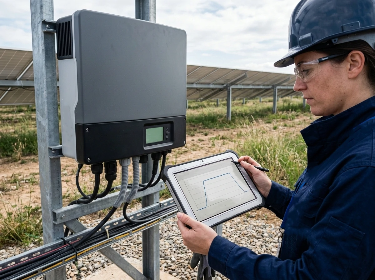
If you’ve ever stared at a production curve and noticed a suspiciously flat top on a bright, cloudless day, you’ve already met the quiet thief in your PV system: solar inverter clipping loss.
It’s subtle. It doesn’t trigger alarms. And most of the time, it’s part of a deliberate design choice.
But here’s the thing: ignore solar inverter clipping loss, and you might be leaving money on the table. Overreact to it, and you could overspend on hardware that never pays for itself.
Let’s dig deep — from physics to finance — and unpack everything you need to know.
Solar inverter clipping loss happens when the DC power produced by your solar array exceeds the AC output capacity of your solar inverter.
When that happens, the inverter “clips” the extra power. It simply cannot convert more than its rated AC capacity, so the output flattens at its maximum.
Picture this:
That difference is solar inverter clipping loss.
Here’s where it gets interesting.
Most modern systems are intentionally designed with a DC/AC ratio greater than 1.0. That means the DC array is larger than the inverter’s AC capacity.
Why? Because modules rarely operate at nameplate power:
Designers use DC/AC ratio optimization to squeeze more energy out of the inverter across more hours of the year.
And yes — that often means accepting some solar inverter clipping loss.
If you’re new to system design, it’s easy to assume that solar inverter clipping loss is something to eliminate at all costs. After all, any “loss” sounds like a mistake.
But here’s the uncomfortable truth: trying to eliminate every bit of solar inverter clipping loss can actually reduce your project’s profitability.
The key is understanding context. Solar inverter clipping loss is not automatically waste. In many well-designed systems, it’s a calculated trade-off rooted in sound engineering and financial modeling.
Let’s break that down.
When we talk about solar inverter clipping loss, we’re really talking about capital efficiency.
Here’s what happens in the real world:
Because of temperature effects, irradiance variability, soiling, and degradation, the DC array only reaches peak theoretical output for a limited number of hours each year. Designing an inverter large enough to avoid all solar inverter clipping loss would mean oversizing for rare peak moments.
That’s rarely economical.
Let’s look at a practical scenario:
In many financial models, the extra inverter cost never pays back.
This is where DC/AC ratio optimization becomes critical. Instead of minimizing solar inverter clipping loss, professionals aim to maximize long-term net present value.
A slightly undersized inverter often produces:
In fact, systems with moderate solar inverter clipping loss frequently show stronger internal rates of return than systems designed for zero clipping.
Another economic nuance: not all kilowatt-hours are equal.
In markets with time-of-use pricing:
If most solar inverter clipping loss occurs during saturated midday peaks — when prices are lower — the financial impact shrinks even further.
From a revenue perspective, losing 2% of annual energy does not automatically mean losing 2% of annual revenue.
That’s why energy yield modeling must always be paired with financial analysis. Focusing on solar inverter clipping loss without evaluating tariff structure is a common rookie mistake.
There’s also a performance principle at play: diminishing marginal gains.
Eliminating the first 1% of solar inverter clipping loss might require modest inverter upsizing. Eliminating the last 1% can become disproportionately expensive.
Experienced designers don’t chase perfection. They chase optimal balance.
And often, that balance includes controlled solar inverter clipping loss.
One of the most common misunderstandings I encounter is confusion between clipping and curtailment. They are fundamentally different — technically and financially.
Understanding that difference protects both performance expectations and investor confidence.
Solar inverter clipping loss occurs when:
It’s a design-driven limitation within the system.
It is predictable.
It is modelable.
And it is part of DC/AC ratio optimization.
Through proper energy yield modeling, including detailed PVsyst clipping data analysis, designers can forecast solar inverter clipping loss before the system is built.
That predictability is critical for bankability.
Curtailment, on the other hand, happens when:
Curtailment is external.
It’s driven by grid conditions — not inverter sizing.
And unlike solar inverter clipping loss, curtailment can be highly variable and sometimes unpredictable.
From an investment standpoint:
Clipping can be quantified accurately using energy yield modeling tools and PVsyst clipping data. Curtailment often requires scenario analysis and sensitivity modeling.
I’ve seen projects where stakeholders misinterpreted flat power curves and assumed grid limitations. After investigation, it turned out to be normal solar inverter clipping loss operating exactly as designed.
That distinction matters.
If you had to choose between:
Most financiers would choose clipping every time.
Why?
Because clipping is:
Curtailment can fluctuate depending on grid upgrades, policy changes, or congestion issues.
In other words, solar inverter clipping loss is often the more manageable risk.
This is the question I hear the most when discussing solar inverter clipping loss:
“Okay, but how much are we really losing?”
It’s a fair question — and an important one. Because without numbers, discussions about solar inverter clipping loss become emotional instead of analytical.
The honest answer? In well-designed systems, the annual energy lost due to solar inverter clipping loss is usually modest. In poorly optimized systems, it can be meaningful. The difference comes down to system design, climate, and how carefully the project was modeled before installation.
Let’s break it down clearly and realistically.
In most professionally designed projects using proper energy yield modeling, annual solar inverter clipping loss falls within a predictable range.
Here’s what we commonly see in the field:
Now, those are averages — not guarantees. The actual number depends heavily on site-specific conditions.
What matters is not the peak clipping moment you see on a monitoring graph. What matters is the annual energy percentage.
A flat top on a power curve might look dramatic. But when you integrate that curve across 8,760 hours in a year, the total solar inverter clipping loss often ends up surprisingly small.
Here’s something many people don’t realize:
Modules rarely operate at full nameplate power.
Real-world conditions reduce DC output:
Because of these factors, your array only exceeds inverter capacity during a limited number of hours each year. That’s why solar inverter clipping loss typically remains in the low single digits annually — even when DC/AC ratios appear aggressive on paper.
This is also why DC/AC ratio optimization is such a powerful tool. By slightly oversizing the DC array, designers increase overall annual production while accepting a manageable amount of solar inverter clipping loss during peak hours.
If DC loading becomes excessive — say above 1.5 without justification — solar inverter clipping loss can climb quickly.
At that point:
This is where proper analysis of PVsyst clipping data becomes critical. Guesswork doesn’t belong in system sizing.
Professional modeling allows you to quantify solar inverter clipping loss before construction, protecting both technical performance and financial projections.
Another important dimension of solar inverter clipping loss is when it occurs.
It does not distribute evenly across the year.
Clipping typically peaks during:
In many climates, this means late spring and early summer — not necessarily the hottest part of summer.
Why?
Because module efficiency drops as temperature rises. Extremely hot weather can actually reduce DC output enough to lower solar inverter clipping loss during peak summer afternoons.
It sounds counterintuitive, but it’s physics.
In colder regions with strong sunlight:
That combination can increase seasonal solar inverter clipping loss compared to very hot regions.
In snowy climates, reflected irradiance (albedo effect) can also temporarily push DC production above inverter limits, creating short bursts of clipping.
Again, this is why energy yield modeling must incorporate accurate meteorological data. Seasonal temperature distribution directly influences expected solar inverter clipping loss.
In winter months:
As a result, solar inverter clipping loss during winter is usually minimal or nonexistent in most fixed-tilt systems.
Tracking systems can change this dynamic slightly, but overall, winter clipping tends to be low.
DC/AC ratio =
Total installed DC module capacity ÷ inverter AC rating.
Example:
This is where DC/AC ratio optimization directly interacts with solar inverter clipping loss.
The trade-off? Increased solar inverter clipping loss.
There is no universal “best” ratio.
But commonly:
Effective DC/AC ratio optimization means modeling scenarios and comparing IRR — not just minimizing solar inverter clipping loss.
If you’re serious about profitability, you don’t guess. You model.
Energy yield modeling allows you to simulate:
Without proper energy yield modeling, you’re designing blind.
When running simulations, tools generate PVsyst clipping data that quantify:
This data tells you exactly how much solar inverter clipping loss you’re accepting.
Look for:
A high DC/AC ratio without proper review of PVsyst clipping data can distort your expectations.
Let’s get practical.
Run multiple scenarios:
Compare:
That’s real energy yield modeling.
Once production differences are known, overlay:
Then determine optimal DC/AC ratio optimization strategy.
Short answer: usually late spring and early summer.
In very hot climates:
So paradoxically, extreme heat can reduce solar inverter clipping loss.
In cooler climates with high irradiance:
This can increase seasonal solar inverter clipping loss.
Now we’re talking investor language.
A 1.4 ratio might:
Despite higher solar inverter clipping loss, net revenue can increase.
If grid export is capped:
Again, solar inverter clipping loss is not inherently negative.
Once you understand that solar inverter clipping loss is partly a design decision, the conversation shifts from “How do I eliminate it?” to “How do I manage it intelligently?”
That’s where advanced system design comes in.
If you’re already working with thoughtful DC/AC ratio optimization and solid energy yield modeling, the next step is refining array configuration and hardware choices to control when and how solar inverter clipping loss occurs.
Because here’s the reality: you may not want to eliminate clipping — but you absolutely want to shape it.
Let’s look at three powerful strategies.
Most traditional PV systems face south (in the northern hemisphere) to maximize annual production. That setup creates a strong midday peak — and that’s exactly when solar inverter clipping loss tends to happen.
East-west orientation changes the game.
Instead of one sharp midday spike, you get:
And that lower peak directly reduces solar inverter clipping loss.
In a south-facing array, the production curve looks like a mountain.
In an east-west design, it looks more like a plateau — wide, but not as tall.
That flatter profile means the inverter is less likely to saturate during peak irradiance hours.
In several rooftop projects I’ve evaluated, shifting to east-west orientation reduced annual solar inverter clipping loss by 1–2% without changing inverter size. At the same time, total annual yield remained competitive due to improved shoulder-hour production.
East-west layouts often allow:
When combined with careful DC/AC ratio optimization, this approach can reduce excessive solar inverter clipping loss while preserving strong annual energy output.
Of course, this strategy must be validated with proper energy yield modeling. Orientation shifts change irradiance angles, shading behavior, and system losses. You never rely on intuition alone.
Bifacial modules introduce another variable into the solar inverter clipping loss equation.
These modules collect irradiance from both the front and rear surfaces. Under high albedo conditions — reflective roofs, light-colored ground, or snow — rear-side gain can significantly boost DC output.
That sounds great.
But here’s the catch: increased DC output can increase solar inverter clipping loss if the inverter capacity remains unchanged.
In systems already operating with high DC/AC ratios, adding bifacial gain can push peak DC power further above inverter limits.
The result?
This doesn’t mean bifacial modules are a bad choice. It simply means their impact must be modeled correctly.
Rear-side gain is highly site-specific:
Without accurate energy yield modeling, including bifacial parameters, you risk underestimating solar inverter clipping loss.
In practice, the right approach is to simulate:
Then compare net annual energy, solar inverter clipping loss, and financial performance.
When done correctly, bifacial systems can increase total annual yield even if solar inverter clipping loss rises slightly. The key is ensuring that the additional rear-side energy more than compensates for any extra clipping.
Tracking systems introduce even greater complexity — and opportunity.
Single-axis trackers follow the sun across the sky, increasing irradiance capture and boosting peak DC production.
That’s good for yield.
But it can significantly increase solar inverter clipping loss if inverter sizing isn’t adjusted accordingly.
Trackers tend to:
In systems with aggressive DC/AC ratios, this combination can create pronounced solar inverter clipping loss during clear-sky conditions.
I’ve reviewed tracker-based systems where clipping exceeded projections simply because designers reused fixed-tilt DC/AC assumptions without re-running full energy yield modeling.
That’s a costly oversight.
To control solar inverter clipping loss in tracking systems, designers often:
Backtracking, in particular, can help reduce excessive peak production while minimizing row-to-row shading. In some climates, this reduces extreme midday spikes and smooths output curves — indirectly managing solar inverter clipping loss.
But again, modeling is everything.
You must evaluate hourly performance data and review clipping breakdowns before locking in design decisions.
Here’s the truth:
Solar inverter clipping loss is not a design flaw. It’s a design decision.
When you understand:
…you stop chasing zero clipping and start chasing maximum returns.
And that shift in mindset? That’s where smart solar design begins.
If you take one thing away from this guide, let it be this:
A little solar inverter clipping loss can be a sign of a well-optimized system.
Ignore it blindly, and you risk inefficiency.
Overreact to it, and you risk overspending.
In most properly designed systems, annual solar inverter clipping loss ranges between 1% and 4%. With aggressive DC loading (1.4–1.5 ratio), losses may reach 5%, but often remain financially acceptable depending on electricity pricing.
In many cases, accepting moderate solar inverter clipping loss is more profitable than installing a larger inverter. The extra energy captured rarely offsets the higher capital cost unless tariffs are exceptionally high.
Use detailed hourly simulations. Adjust DC/AC ratio and review PVsyst clipping data within the loss diagram and detailed report. Compare multiple scenarios as part of your energy yield modeling process to determine optimal DC/AC ratio optimization.
It typically occurs during clear, cool, high-irradiance periods. In very hot climates, high temperatures reduce DC output and may decrease solar inverter clipping loss during peak summer.
A 1.4 ratio increases solar inverter clipping loss but often improves overall energy yield and financial performance. When properly modeled using energy yield modeling tools, it can lower LCOE and boost IRR.